
A medium-voltage DC fault current limiter and its implementation method

A current limiter, DC fault technology, applied in the direction of emergency protection circuit devices, electrical components, circuit devices for limiting overcurrent/overvoltage, etc. The current efficiency is not high, the response speed is slow, etc., to reduce the arc energy consumption, the response speed is fast, and the arc voltage is improved.

Inactive Publication Date: 2019-04-16
XI AN JIAOTONG UNIV +1
View PDF4 Cites 0 Cited by
  • Summary
  • Abstract
  • Description
  • Claims
  • Application Information

AI Technical Summary

Problems solved by technology

[0003] The magnetic contraction liquid metal current limiter has a fast response speed but the current limiting efficiency is not high. Although the movable liquid metal current limiter has a strong current limiting ability, the response speed is slow

Method used


Image

  • A medium-voltage DC fault current limiter and its implementation method
  • A medium-voltage DC fault current limiter and its implementation method
  • A medium-voltage DC fault current limiter and its implementation method

Examples


Embodiment Construction

[0023] The structure and working principle of the present disclosure will be further described in detail below with reference to the accompanying drawings.

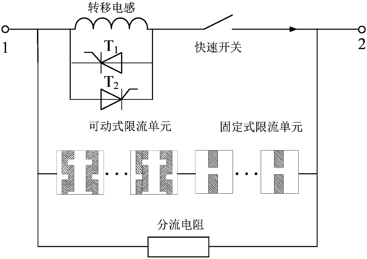
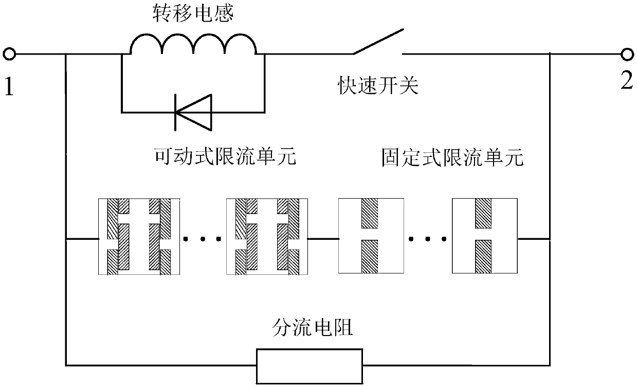
[0024] In one embodiment, the present disclosure discloses a medium voltage DC fault current limiter, the current limiter comprising: a fast switching branch, a current limiting unit branch and a shunt resistance branch;

[0025] The fast switching branch is used to transfer the fault current to the current limiting unit branch when a short-circuit fault occurs in the DC power supply system;

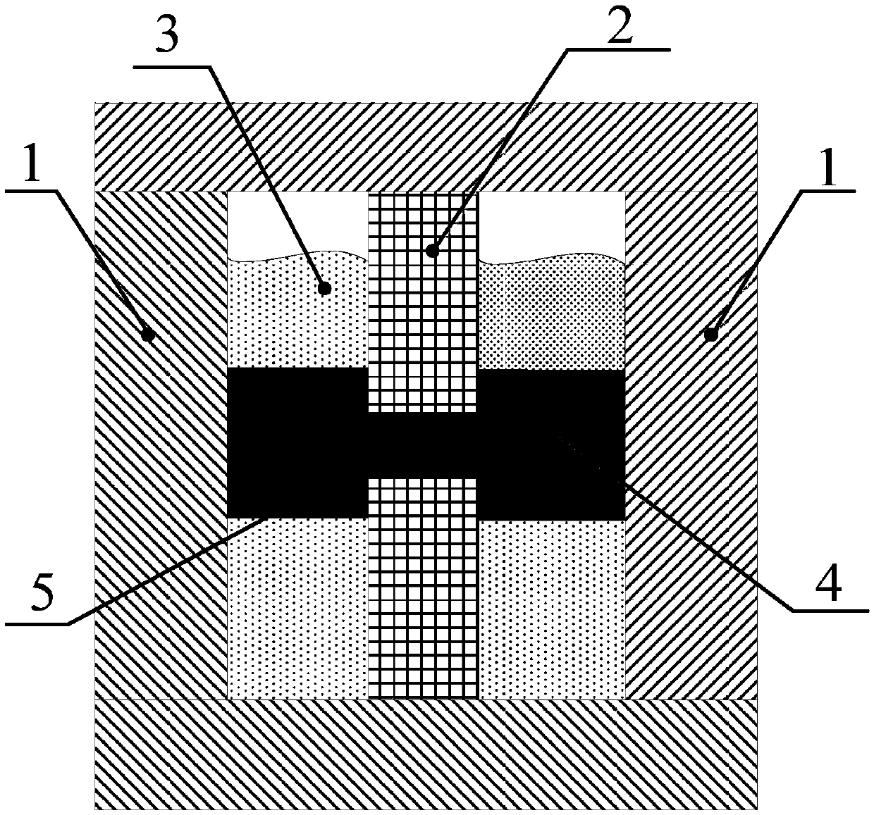
[0026] The current limiting unit branch includes at least one fixed liquid metal current limiting unit and at least one movable liquid metal current limiting unit, and the current limiting unit branch is used to limit the fault current to a lower level;

[0027] The shunt resistor branch is used to bear part of the fault current when a short-circuit fault occurs in the DC power supply system.

[0028] In this embodiment, the soluti...


PUM


Abstract

The disclosure discloses a medium-voltage direct-current fault current limiter and an implementation method thereof. The current limiter comprises a fast switching branch, a current-limiting unit branch and a shunt resistance branch. The fast switching branch employs a fast mechanical switch to realize rated flowing. The current-limiting unit branch is formed by series connection of a plurality offixed liquid metal current-limiting units and a movable liquid metal current-limiting unit to realize respectively fault current peak limiting and short-circuit energy dissipation. The shunt resistance branch is a resistor; in a current-limiting state, the short-circuit energy is shared and thus the current-limiting unit is protected. According to the disclosure, the parts are reduced and thus the structure becomes simple. Functions of rated high-current carrying and fast short-circuit current limitation are realized simultaneously and rapid transfer and short-circuit energy dissipation problems of the heavy-direct-current fault currents are solved. The limiter and implementation method thereof are especially suitable for limiting the fault current of the medium-voltage direct-current system, so that burdens of various electrical devices like a circuit breaker are reduced.

Description

technical field [0001] The present disclosure relates to a DC system fault current limiter, in particular to a medium-voltage DC fault current limiter and an implementation method thereof. Background technique [0002] With the rapid development of my country's economy and the gradual modernization of the industrial transportation sector, the requirements for the capacity of the DC power supply system are increasing, and the short-circuit capacity and short-circuit current level of the DC power grid are also increasing. Meet the short-circuit capacity requirements of medium-voltage DC power grids. Therefore, an effective DC fault current limiter is studied to limit the short-circuit capacity of the DC power system, thereby reducing the design requirements of the DC circuit breaker and improving the operational reliability of the power system. So far, the self-recovery liquid metal current limiting technologies used in DC fault current limiting mainly include: magnetic shrink...

Claims


Application Information

Patent Timeline
Patent Type & Authority Patents(China)
IPC IPC(8): H02H3/087H02H9/02
Inventor 吴翊何海龙荣命哲杨倬吕思雨
Owner XI AN JIAOTONG UNIV
Learn More