Pantograph projection

a pantograph and projection technology, applied in the field of sewing, can solve the problems of difficult operation of the stitcher using the pantograph method known in the art, difficulty in aligning paper patterns at the rear of the machine, and hand quilting was done by hand

Active Publication Date: 2017-05-16
GAMMILL
View PDF7 Cites 12 Cited by
  • Summary
  • Abstract
  • Description
  • Claims
  • Application Information

AI Technical Summary

Benefits of technology

[0011]The one or more projection units may be in electrical and / or data communication with the computer device of the present invention such that a pantograph pattern may be loaded from the computer device and transmitted to the one or more projection units such that the projection unit may display the pantograph pattern to be traced. By tracing the pantograph pattern with the needle and thread, the operator can ensure that the needle and thread at the front portion of the head produces the same pattern in front of and below the fabric. In operation, the projected pattern may be tied into measurement devices, for example encoders, associated with the computer device such that the measurement devices may determine head movement and continually adjust the pattern accordingly.

Problems solved by technology

Traditional quilting was done by hand and was very labor intensive.
Needing to operate the machine from the rear further may require that control devices and other equipment be placed at the rear of the head that would otherwise be unnecessary and may even be duplicative.
Operating the stitcher using pantograph methods known in the art may also be somewhat difficult.
For example, it may be challenging to align paper patterns at the rear of the machine, and / or it may be difficult to align lasers for tracing the pantograph patterns.
In attempting to align and position paper pantograph patterns, the paper patterns may become damaged or torn.
Also, when using paper patterns, storing and keeping the patterns from being damaged can be difficult.

Method used


Image

  • Pantograph projection
  • Pantograph projection
  • Pantograph projection

Examples


Embodiment Construction

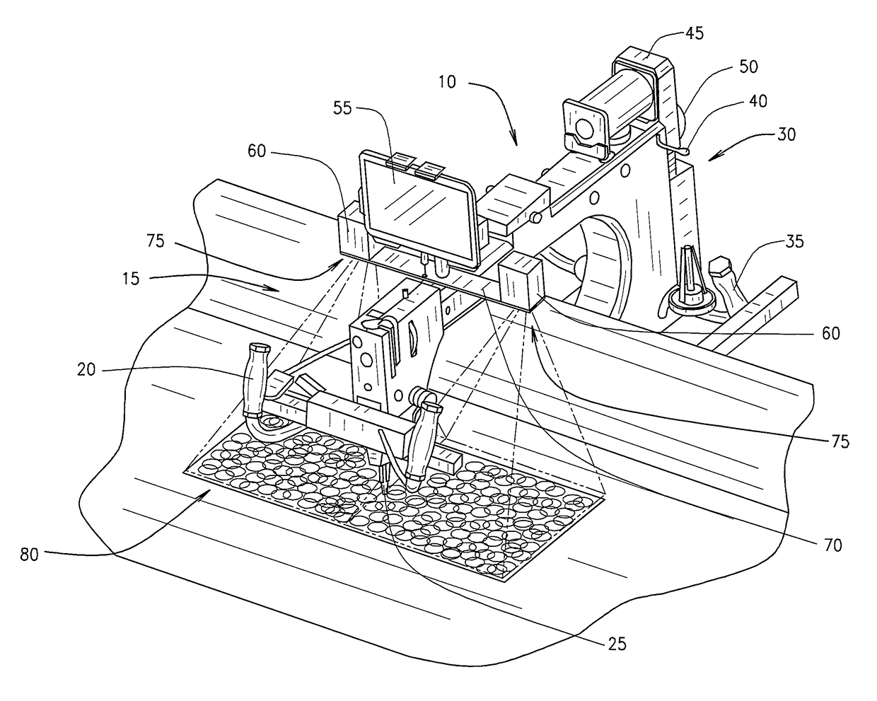
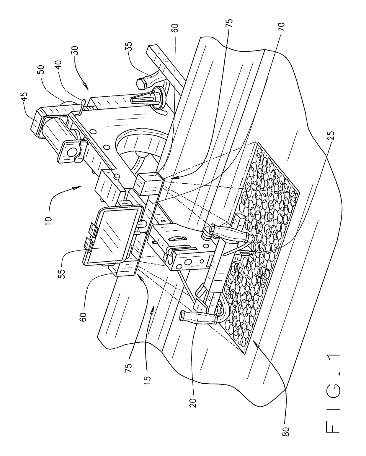
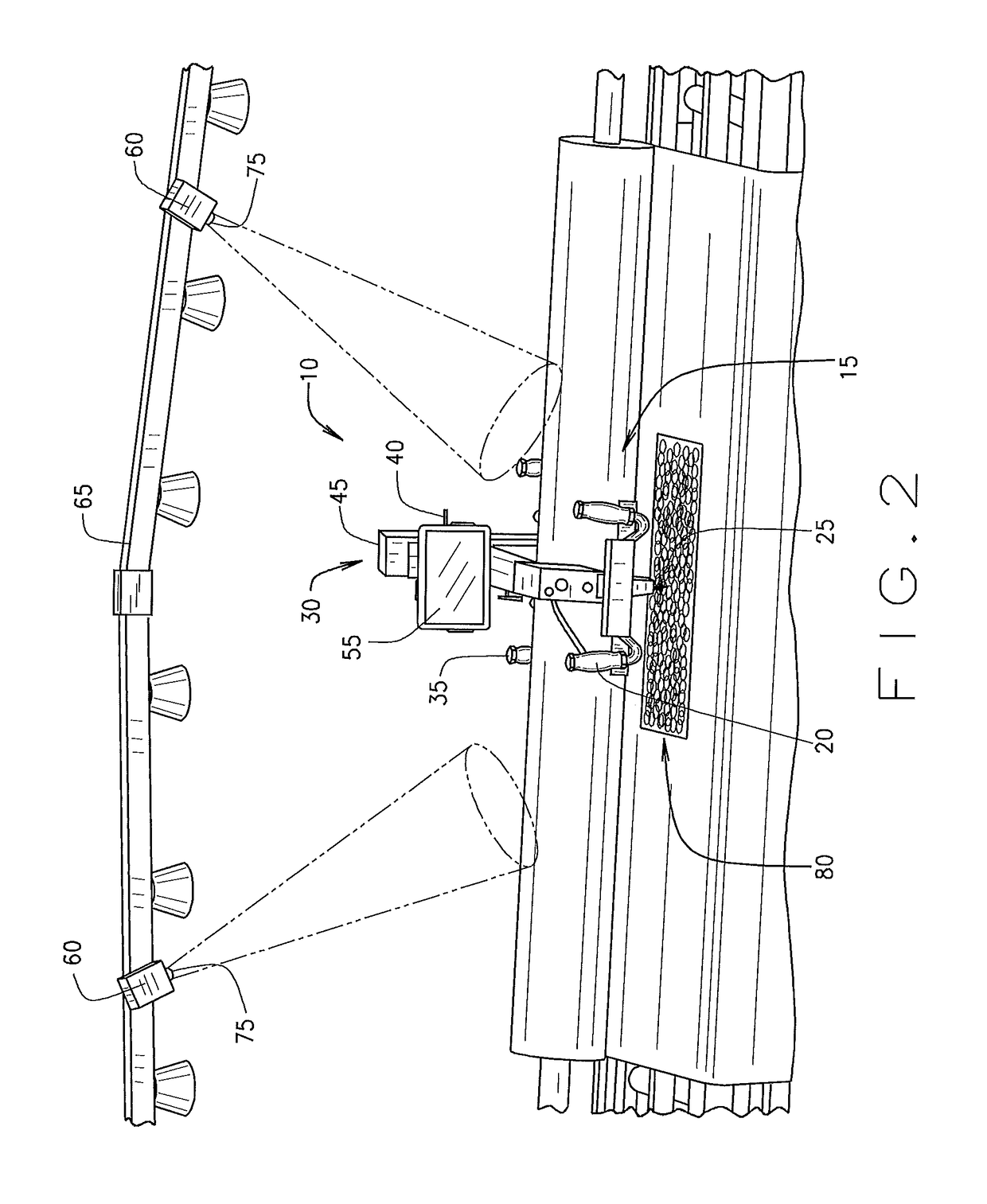
[0016]The present invention is directed generally toward a sewing machine including a means for projecting a pantograph pattern on quilt fabric such that the fabric including the pantograph pattern may be traced to stitch a pattern thereon. FIGS. 1 and 2 illustrate a perspective view of a sewing machine head 10 for use with a long-armed sewing machine, or long-armed stitcher. As illustrated, the sewing machine head 10 includes a plurality of components that are known in the art. For example, sewing machine head 10 includes a front portion 15 where a first set of handles 20 are positioned and located for moving the sewing machine head 10 above a quilt such that needle 25 may stitch a desired pantograph pattern onto the quilt positioned and located below the sewing machine head 10 in a long-armed stitcher arrangement known in the art.

[0017]At rear portion 30 of the sewing machine head 10, the sewing machine head 10 further may comprise a second set of handles 35 that are positioned an...


PUM


Abstract

The present invention relates to a sewing machine, specifically a long-armed stitcher. The present invention includes a computer device that may store pantograph patterns therein. The data including the pantograph patterns may be sent to projection units associated with the sewing machine head of the long-armed stitcher. The projection units use projection elements to project the pantograph patterns on the fabric to be stitched, allowing an operator of the stitcher to trace the projected pattern with a needle associated with the sewing machine head. Measurement devices associated with the sewing machine head determine head movement and alter the projected pattern accordingly such that the needle of the sewing head may continue to follow the pantograph pattern despite the head having moved in order to trace the pattern.

Description

BACKGROUND OF INVENTION[0001]The present invention relates to sewing, and more particularly, to particular styles and techniques of sewing that incorporate decorative stitching such as quilting. A quilt is a type of blanket typically having three layers: a decorative top layer, a middle layer of insulating material, and a backing layer. “Quilting” refers to the technique of joining these layers by stitches or ties.[0002]Traditional quilting was done by hand and was very labor intensive. The invention of the sewing machine changed that tradition. Quilting evolved from production of functional blankets by specialized artisans into a popular hobby enjoyed by many.[0003]Modern quilts are typically made using a long-armed sewing machine, or stitcher, attached to a frame. The frame supports and holds the workpiece in place while the sewing machine moves along the frame with respect to the workpiece. A typical quilting apparatus illustrating the relationship between the workpiece, frame, a...

Claims


Application Information

Patent Timeline
Patent Type & Authority Patents(United States)
IPC IPC(8): D05C5/02D05B81/00D05B19/12D05B19/08
CPCD05B19/12D05B19/08D05B81/00
Inventor ELLIOTT, DANIEL LEEBAUMAN, JOSEPH WESLEYLANGFORD, BETTILOU KENNEY
Owner GAMMILL
Why Eureka
Try Eureka