Method of controlling a machine connected to a display by line of vision

a technology of line of vision and display, which is applied in the direction of instruments, computing, electric digital data processing, etc., can solve the problems of inefficiency of mouse and keyboard use, mouse is not suited as text input device, and the patent does not disclose the method of hands-free pointer control (using buttons)

Inactive Publication Date: 2006-09-21
FENGELS MR DIRK
View PDF4 Cites 81 Cited by
  • Summary
  • Abstract
  • Description
  • Claims
  • Application Information

AI Technical Summary

Benefits of technology

[0055] It is a primary objective of this invention to provide an intuitive and precise hands-free method of controlling a machine that is connected to a display, such as a computer with monitor or a gaming device connected to a TV. To also eliminate the need to periodically switch between text input device and pointing device.

Problems solved by technology

However, a mouse is not suited as a text input device, where keyboards are most effective.
Operating in an environment such as Microsoft Windows where pointing and initiating actions as well as text input are required, the use of mouse and keyboard is not efficient since the user must frequently switch between the mouse and the keyboard.
Said patent however does not disclose a method of hands-free pointer control (uses buttons) and especially is not correlated to the line of sight or line of vision of the operator.
The disclosure further describes means for initiating actions by rapid movements such as horizontal and vertical nodding, resulting in a very limited number of possibilities to initiate actions.
However, there is no disclosure of hands-free pointer control on a display connected to a machine.
U.S. Pat. No. 5,367,315 uses eye and head movement to control a cursor; however the method only detects direction of eye movement to move the cursor in the same direction and does not detect the absolute line of vision with respect to a display.
Also, the operating range is limited to an active area within which the operator must remain.
All head tracking methods translating relative head movements into pointer movements suffer from the disadvantage that the pointer position is not directly correlated to the line of vision or focus point of the operator.
This requires permanent visual feedback when the pointer is moved and lacks intuitive use because without visual feedback the operator is unaware of and cannot know the current pointer position.
In addition, some head tracking methods use one or multiple stationary sensors affixed with respect to the display that result in increased system complexity and limitations regarding posture and position of the operator with respect to the display due to a limited field of view of the sensors.
This patent also lacks absolute pointer control and correlation between pointer control and line of vision and therefore intuitive use.
These consumer products lack absolute pointer control and direct correlation between pointer control and line of vision.
This method can only constitute a pseudo absolute control and it still lacks correlation to line of vision even if the system were frequently recalibrated.
Further, these consumer products often lack means for initiating a large variety of actions.
They also require software algorithms with significant computational power requirements.
This is a serious disadvantage for the normal user.
Said limitation is that the user must turn his or her head along with the eyes or, in other words, the user must keep relative eye-head movements small.
Even with this limitation, the use of such a device is very intuitive since people tend to move their head with their eyes to keep eye movements small and only minor adjustments need to be made to move the pointer onto the target.
Thus, all pointing methods heretofore known suffer from at least one but often multiple of disadvantages: (1) The use of mouse and keyboard is not very efficient since the user must frequently switch between mouse and keyboard.
Thus, relative pointer control is not highly intuitive.
(3) May cause physiological problems such as carpel tunnel syndrome.
(6) Static sensor position(s) with respect to the display, causing restrictions in the position or freedom of movement and posture of the operator due to a limited field of view of the sensor(s).
(7) Methods using image-processing algorithms to detect certain parameters such as eye positions require a lot of computational power.
Such methods are likely to lack intuitive use and precision.
(12) Sensors are used that are lower performance than charge coupled device (CCD) or CMOS image sensors regarding speed, power consumption, size, weight and resolution and thus precision or sensors are much more expensive.
This reduces the computational power required by the processor or software driver.

Method used


Image

  • Method of controlling a machine connected to a display by line of vision
  • Method of controlling a machine connected to a display by line of vision
  • Method of controlling a machine connected to a display by line of vision

Examples


Embodiment Construction

—FIGS. 1, 2, 3, 5—PREFERRED EMBODIMENT
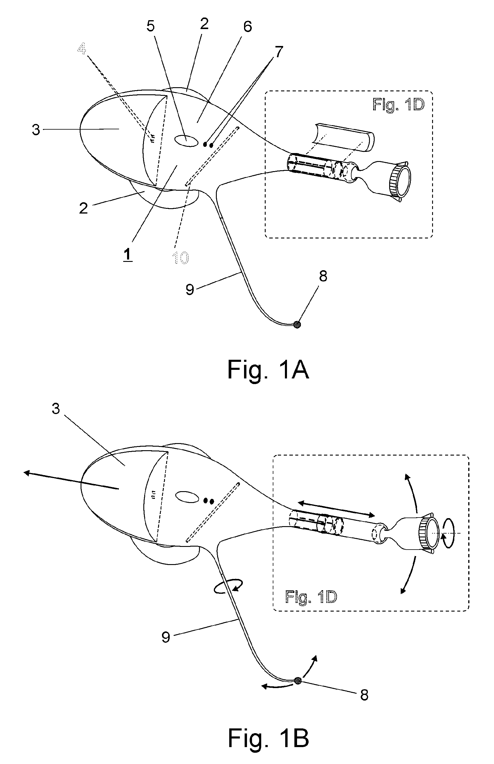
[0074] FIGS. 1A-1D:

[0075]FIGS. 1A to 1D show a preferred embodiment of the form factor of the wearable apparatus in different perspective views. FIG. 1A shows the main body 6 containing electronic components and a rechargeable battery 3 inserted into the main body. The entire case of the apparatus is plastic or another lightweight material. The battery is detachable from the main body as indicated by the arrow in FIG. 1B and when inserted, it is connected to the electronic circuitry inside the main case over two contacts 4.

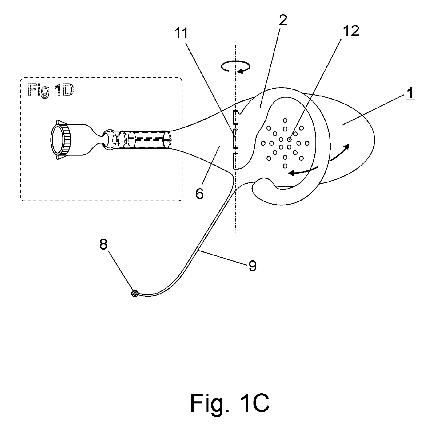
[0076] A C-shaped ear clip 2 is attached to the main body, best shown in FIG. 1C. The ear clip consists of a flexible wire, coated in a soft material like rubber or plastic and its shape is designed to fit around a human ear to hold the main body in a stable position next to the ear. It can be manipulated to fit an individual ear.

[0077]FIG. 1D shows a more detailed, exploded view of the front end of the preferred embodiment...


PUM


Abstract

A method of controlling a machine connected to a display comprising an absolute pointing method providing a wearable apparatus (1) including an image sensor (61) worn on an operator's head (58) or ear and adjustable so that the pointing direction (57) of the image sensor (61) is congruent with the operator's focus point on said display (45) when relative head-eye movements are small. A processor (33) analyzes images (103) of the display environment taken by the image sensor (61) and determines the pointing direction (57) of the image sensor with respect to the display outline (50). The wearable apparatus (1) further includes a microphone (8) for initiating actions on said machine by audio commands. Other means for initiating actions includes detecting certain head movements and a special keyboard driver. The method further comprises means for feedback from the wearable apparatus (1) to the machine. A wireless configuration is provided, including a receiver apparatus (42) connected to the machine, where a software driver positions the pointer (51) on the display area (55) and responds to operator commands. Means for facilitating display outline recognition to increase performance and reliability is provided and consists of no more than eight infrared reflective stickers (49) placed around the perimeter of the display area (55) and an infrared source (19) located next to the image sensor (61).

Description

BACKGROUND OF THE INVENTION [0001] 1. Field of Invention [0002] This invention relates to hands-free pointing devices or methods with means for initiating actions on a machine connected to a display, specifically to devices or methods which correlate pointer positioning on a display with line of vision or focus point of the operator. [0003] 2. Prior Art [0004] Many machines with a display require user interaction over pointing devices or other input devices. Machines with graphical displays are effectively controlled by pointing devices such as a mouse if the machine is a computer. A mouse enables pointing to certain objects on the screen and initiating an action by pressing a button. However, a mouse is not suited as a text input device, where keyboards are most effective. Operating in an environment such as Microsoft Windows where pointing and initiating actions as well as text input are required, the use of mouse and keyboard is not efficient since the user must frequently switch...

Claims


Application Information

Patent Timeline
Patent Type & Authority Applications(United States)
IPC IPC(8): G09G5/00
CPCG06F3/0325
Inventor FENGELS, DIRK
Owner FENGELS MR DIRK
Why Eureka
Try Eureka