In-ear device incorporating active noise reduction

a technology of active noise reduction and in-ear devices, which is applied in the direction of electrical transducers, mouthpiece/microphone attachments, instruments, etc., can solve the problems of reducing the overall size of the device, affecting the performance of the device, and affecting the stability of the device, so as to improve the effect of active noise cancellation performan

Inactive Publication Date: 2017-05-16
PHITECK SYST LTD
View PDF123 Cites 19 Cited by
  • Summary
  • Abstract
  • Description
  • Claims
  • Application Information

AI Technical Summary

Benefits of technology

[0008]It is an object of the invention to provide improved active noise cancellation performance in an in-ear device or to at least provide the public with a useful alternative to existing devices.
[0025]In one embodiment the impedance is selected to improve stability of the device when used in an active noise reduction feedback or hybrid control architecture.
[0034]an acoustic impedance provided in the acoustic path adapted to limit the dynamic of the system and improve stability of the device.
[0037]In another aspect the invention provides a method of improving the stability of an in-ear device having:
[0043]the method comprising providing an acoustic impedance in the acoustic path which is sufficient to improve the stability of the device.

Problems solved by technology

In particular, stability is an issue as the load condition of the device can greatly affect the open loop transfer function (OLTF).
Further miniaturisation is only exacerbating these issues.
In addition, moving the electronics required to create a feedback controller, or part thereof, inside the housing would require considerable miniaturisation of the acoustic system to achieve a decrease in overall size of the device and consequently a carefully tuned OLTF would be required to reduce the necessary controller complexity to design a high performance noise cancellation system.

Method used


Image

  • In-ear device incorporating active noise reduction
  • In-ear device incorporating active noise reduction
  • In-ear device incorporating active noise reduction

Examples


Embodiment Construction

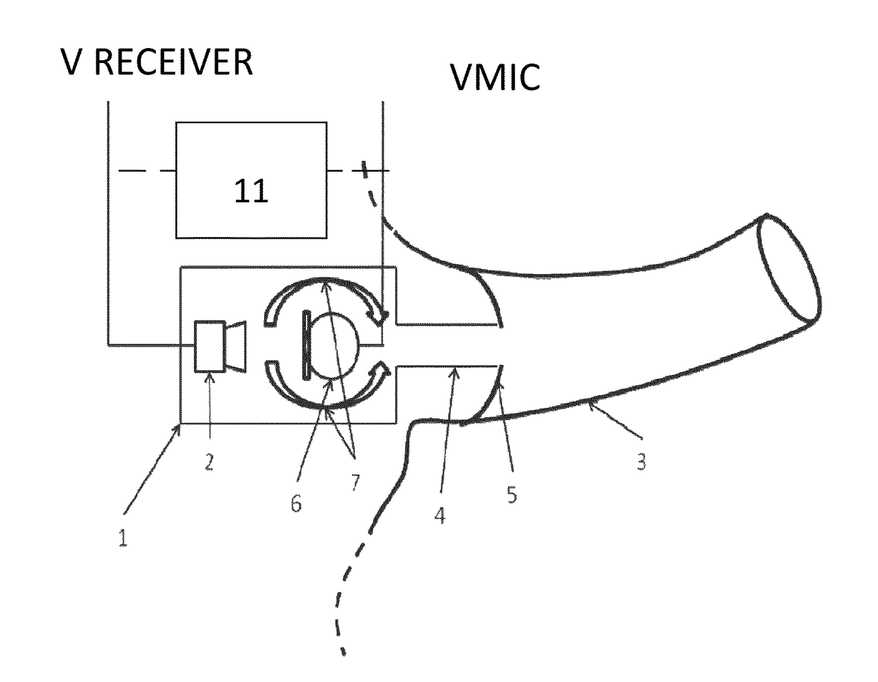
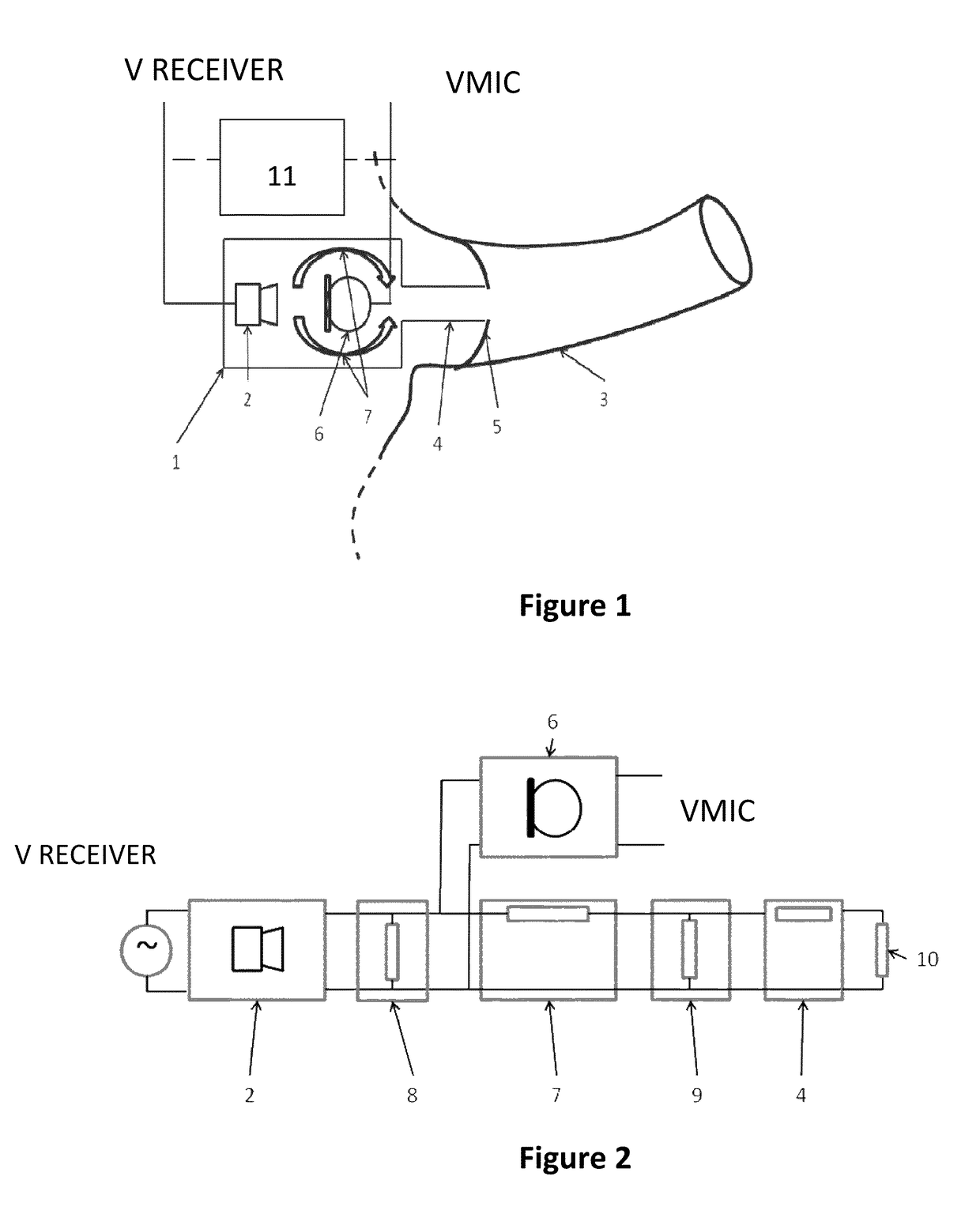
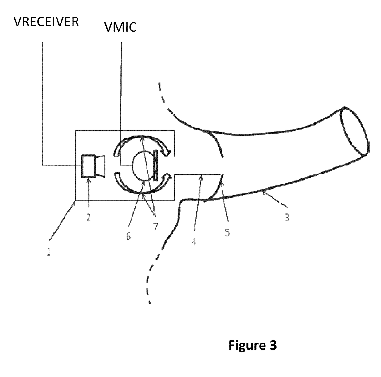
[0062]The present invention relates specifically to the design of the acoustic path or conduit between the driver and the outlet of the device. In some embodiments the invention is realised in the design of the conduits / passageways through which sound is conducted around the microphone. The acoustic impedance of these elements may be designed so as to engineer the electro-acoustic transfer function between the input to the driver and the output from the microphone, which constitutes (a component of) the “open-loop transfer function” (OLTF) of the “system-under-control” or “plant” (to use the terminology of automatic control). This transfer function is a key determinant of system stability and noise cancelling performance. The desired improvement in robustness of the closed loop system is achieved by decreasing the dynamic (i.e. the variation) of the OLTF with regard to vulnerability and sensitivity of the earphone to varying load conditions. Those skilled in the art will understand ...


PUM


Abstract

An in-ear device incorporating active noise reduction has a housing adapted for location in or adjacent to an auditory canal. The housing contains a driver and an acoustic path is provided from the driver to an outlet of the device. A microphone and an acoustic impedance are provided in the acoustic path. The impedance increases the stability of the device.

Description

[0001]This is a utility application that claims the benefit of and priority from U.S. Provisional Patent Application Ser. No. 61 / 491,983, filed Jun. 1, 2011.FIELD OF THE INVENTION[0002]This invention relates to in-ear devices incorporating active noise reduction. Such devices include but are not limited to earphones, “in-ear monitors”, hearing aids and similar assisted listening devices. Moreover, the term “in-ear” includes devices that may be partially located in the human auditory canal.BACKGROUND[0003]The active noise reduction functionality relevant to the present invention is realized using “feedback” or hybrid (a combination of feedback and feed-forward) control architectures, in which a or a plurality of sensors which include but are not limited to a microphone is located inboard (i.e. closer to the wearer's ear) of the “receiver” (miniature loudspeaker or driver) in the device. The output of the microphone is used to provide the observation required for feedback (or equivale...

Claims


Application Information

Patent Timeline
Patent Type & Authority Patents(United States)
IPC IPC(8): H04R1/10H04R1/08H04R1/28
CPCH04R1/083H04R1/2838H04R2460/01H04R1/1083
Inventor DARLINGTON, PAULAZMI, YACINELEFEBVRE, MICKAEL BERNARD ANDREHEWITT, OLIVER MICHAEL JAMES
Owner PHITECK SYST LTD
Why Eureka
Try Eureka