Systems and methods for supporting zones in a monitoring system

a monitoring system and monitoring system technology, applied in the field of monitoring movement, can solve the problems of wasting productivity and housing expense, and unable to determine which specific defined region over a large region has been entered by a monitored individual, and achieves the effect of reducing the number of monitoring stations

Active Publication Date: 2017-05-30
BI
View PDF20 Cites 25 Cited by
  • Summary
  • Abstract
  • Description
  • Claims
  • Application Information

AI Technical Summary

Problems solved by technology

This represents a significant cost to society both in terms of housing expense and wasted productivity.
In some cases, determining w

Method used


Image

  • Systems and methods for supporting zones in a monitoring system
  • Systems and methods for supporting zones in a monitoring system
  • Systems and methods for supporting zones in a monitoring system

Examples


Embodiment Construction

[0015]The present invention is related to monitoring movement, and in particular to systems and methods for monitoring.

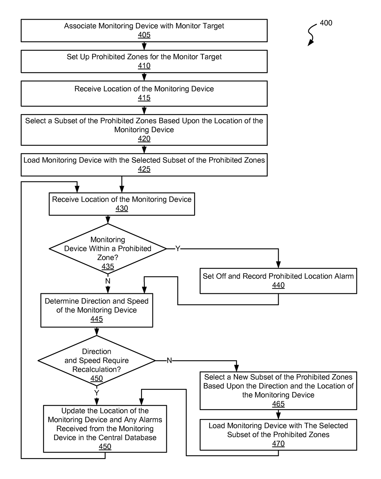
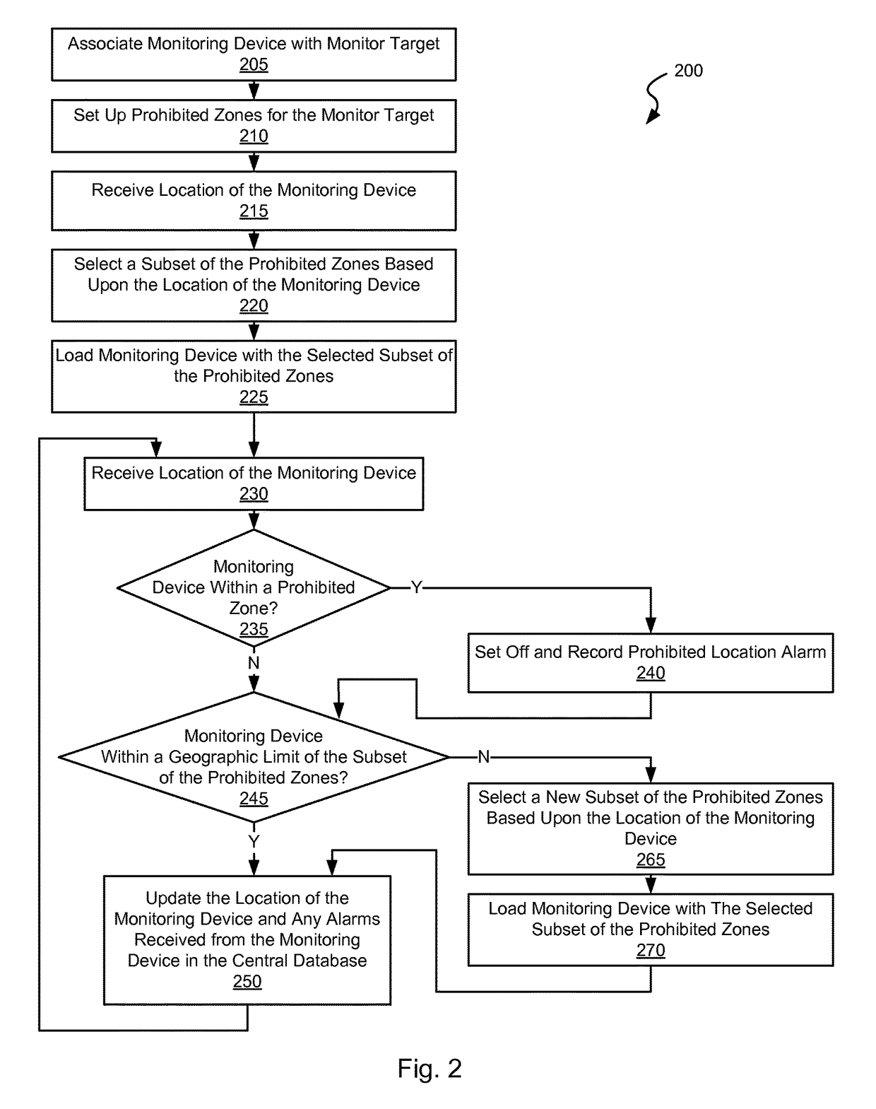
[0016]Various embodiments of the present invention provide for tracking or monitoring an individual, animal or object. As used herein, the phrase “target” is used in its broadest sense to mean any individual, animal or object. The embodiments provide an ability for determining whether a monitoring device and therefore a monitoring target, has entered into a prohibited zone over a wide area while limiting the memory and processing required to make the determination. Such embodiments allow for updating of prohibited zones on an automated basis based upon, for example a location of the monitoring device, a speed and direction of a monitoring device, a time since the monitoring device was last updated, or other trigger.

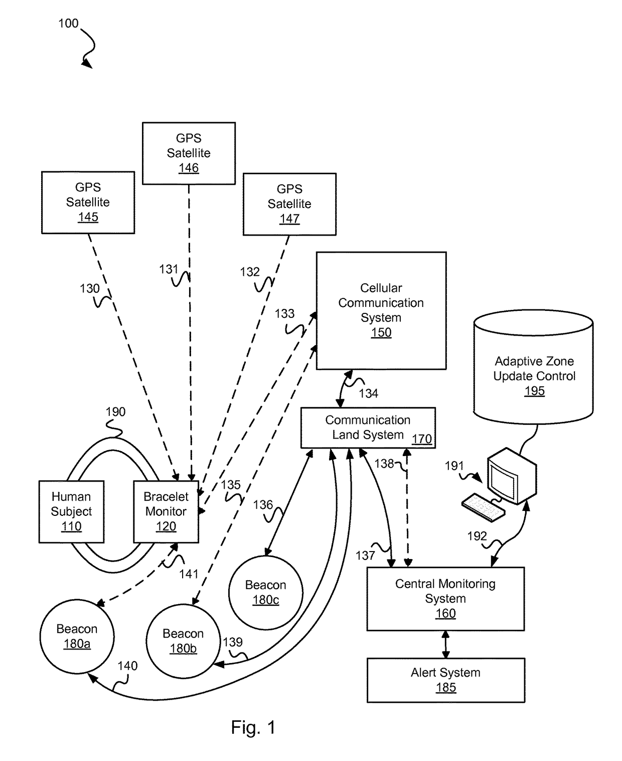
[0017]Various embodiments of the present invention provide monitoring systems that include: a monitoring device associated with a monitor target where th...


PUM


Abstract

Various embodiments of the present invention provide systems and method for adaptive monitoring of physical movement.

Description

CROSS REFERENCE TO RELATED APPLICATION[0001]The present application claims priority to (i.e., is a non-provisional of) U.S. Pat. App. No. 61 / 670,094 entitled “Systems and Methods for Supporting Zones in an Offender Tracking System”, and filed Jul. 10, 2012 by Newell et al. The entirety of the aforementioned application is incorporated herein by reference for all purposes.BACKGROUND OF THE INVENTION[0002]The present invention is related to monitoring movement, and in particular to systems and methods for monitoring.[0003]Large numbers of individuals are currently housed in prisons. This represents a significant cost to society both in terms of housing expense and wasted productivity. To address this concern, house arrest systems have been developed for use by less violent offenders. This allows the less violent offender to be monitored outside of a traditional prison system and allows the offender an opportunity to work and interact to at least some degree in society. The same approa...

Claims


Application Information

Patent Timeline
IPC IPC(8): H04W24/00H04W4/02H04W4/021
CPCH04W4/021H04W4/02H04W4/027
Inventor NEWELL, JOSEPH P.BUCK, JAMES J. JR.
Owner BI
Why Eureka
Try Eureka