Chain link using a pressed-in member

a technology of chain link and pressed member, which is applied in the direction of hoisting chains, metal chains, and carrying chains, etc., can solve the problems of occupying valuable space, occupying a large amount of time, and the length of the apparatus used in heat treating the chain may be undetectedly long and expensive to constru

Active Publication Date: 2017-06-06
CATERPILLAR INC
View PDF21 Cites 4 Cited by
  • Summary
  • Abstract
  • Description
  • Claims
  • Application Information

AI Technical Summary

Problems solved by technology

The drawbacks to this design include the amount of time it takes to cast the chain, the obstacles with pouring the chain and avoiding casting defects, heat treating the entire length of the chain as well as the space needed to quench the chain, and the time to model the chain assembly.
In particular, the length of the apparatus used in heat treating the chain may be undesirably long

Method used


Image

  • Chain link using a pressed-in member
  • Chain link using a pressed-in member
  • Chain link using a pressed-in member

Examples


Embodiment Construction

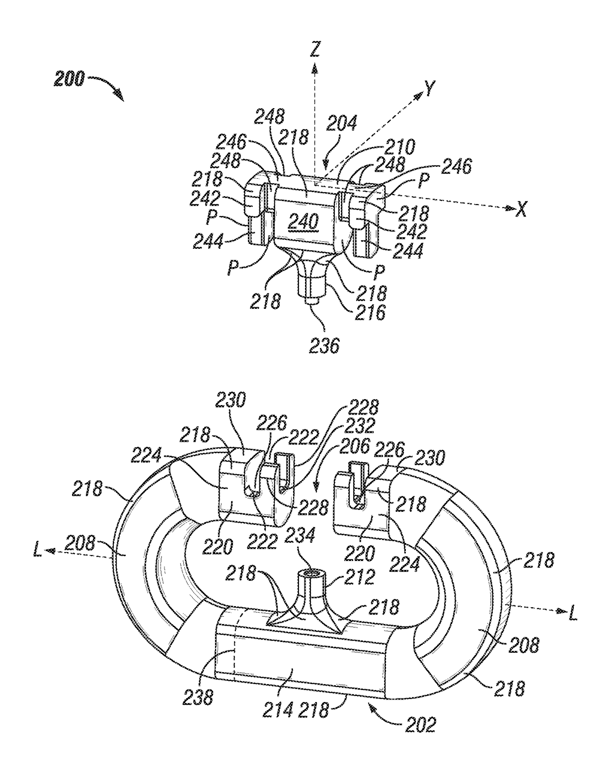
[0017]The solution is to have a two piece link joins whole body links together. The joining process involves a “tee” section that is press fit (every other link) to make a chain assembly. This allows the ability to cast individual components, heat treat to the desired specification then assemble the chains. This also will eliminate the welding aspect to assemble the chain links together, thus saving time and assembly cost. The press fit allows for load transfer within the individual link assembly, eliminates welding, and eliminates the need to cast the chain as a single assembly. It also allows for final heat treating to be conducted prior to chain assembly. The chain may then be painted and placed into distribution.

[0018]Focusing now on FIGS. 5 and 6, a chain link subassembly 200 according to an embodiment of the present disclosure is shown. The chain link subassembly 200 includes a main link member 202 and a press-in member 204 or connecting member that is intended to be attached ...


PUM


Abstract

A method of forming a chain having a plurality of links that are formed from separate link members is provided that includes press fitting one link member into another link member. The method may further comprise cooling or heating one link member before completing the pressing operation.

Description

TECHNICAL FIELD[0001]The present disclosure relates to chain assemblies that are constructed from links formed from separate parts. More specifically, the present disclosure relates to a dragline bucket chain assembly that includes a chain link that includes two members that are pressed into a subassembly.BACKGROUND[0002]Referring initially to FIG. 1, chains 100 have historically been used in dragline buckets 102 in the hoist and drag circuits. Some rigging configurations also use chains in the dump circuit (single dump block systems). Chains 100 have in the past been cast, forged, comprised structural plate, etc.[0003]Looking now at FIG. 2, an example of a dragline bucket chain 100, which is cast as one assembly is shown. The drawbacks to this design include the amount of time it takes to cast the chain, the obstacles with pouring the chain and avoiding casting defects, heat treating the entire length of the chain as well as the space needed to quench the chain, and the time to mod...

Claims


Application Information

Patent Timeline
IPC IPC(8): F16G15/02B21L11/00F16G15/12
CPCF16G15/02F16G15/12B21L11/00F16G13/14
Inventor STOLZ, MICHAEL ROBERT
Owner CATERPILLAR INC
Why Eureka
Try Eureka