Test connector retaining harness assembly

a technology of test connectors and harnesses, which is applied in the direction of coupling device connections, instruments, measurement instrument housings, etc., can solve the problems of affecting the test equipment or components of the aircraft, the time it takes to disconnect a single test connector from the shipside connector may exceed thirty minutes, and the connector parts are damaged

Active Publication Date: 2017-06-27
THE BOEING CO
View PDF5 Cites 2 Cited by
  • Summary
  • Abstract
  • Description
  • Claims
  • Application Information

AI Technical Summary

Benefits of technology

[0007]Certain embodiments of the present disclosure provide an electrical system that may include a first electrical connector (such as a shipside connector within a galley of an aircraft) configured to be coupled to an electrical panel, a second electrical connector (such as test connector) configured to be coupled to a testing device that is configured to test components coupled to the electrical panel, and a retaining harness assembly that removably connects to the first and second electrical connectors to maintain a secure mating relationship between the first and second electrical connectors.
[0011]In at least one embodiment, the retaining harness assembly may include a retainer housing secured around a portion of a backshell of the first electrical connector, a spring override ring secured around a portion of the retainer housing and operatively coupled to a torque ring of the first electrical connector, and a biasing spring having a first end retained by the retainer housing. The spring override ring may be configured to be rotated between a first position in which the biasing spring biases the spring override ring into the torque ring, and a second position in which the biasing spring is compressed toward the retainer housing. Compression of the biasing spring toward the retainer housing allows the torque ring to be rotated.

Problems solved by technology

Often, the time it takes to disconnect a single test connector from the shipside connector may exceed thirty minutes.
The force used to disconnect the connectors, as well as the awkward positions used to engage the torque ring with one or more strap wrenches, may lead to discomfort and injuries.
Further, the high levels of force used to disconnect the test connector from the shipside connector may cause damage to portions of the connectors, testing equipment, or components within the aircraft.
Due to the awkward wrist position, an individual may be susceptible to injury.
In general, the task of disconnecting a test connector from a shipside connector within a galley of an aircraft represents a high risk procedure that leads to numerous hand and wrist injuries.

Method used


Image

  • Test connector retaining harness assembly
  • Test connector retaining harness assembly
  • Test connector retaining harness assembly

Examples


Embodiment Construction

[0028]The foregoing summary, as well as the following detailed description of certain embodiments will be better understood when read in conjunction with the appended drawings. As used herein, an element or step recited in the singular and preceded by the word “a” or “an” should be understood as not necessarily excluding the plural of the elements or steps. Further, references to “one embodiment” are not intended to be interpreted as excluding the existence of additional embodiments that also incorporate the recited features. Moreover, unless explicitly stated to the contrary, embodiments “comprising” or “having” an element or a plurality of elements having a particular property may include additional elements, which may or may not include that property.

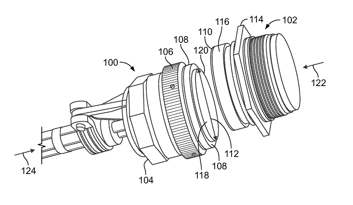
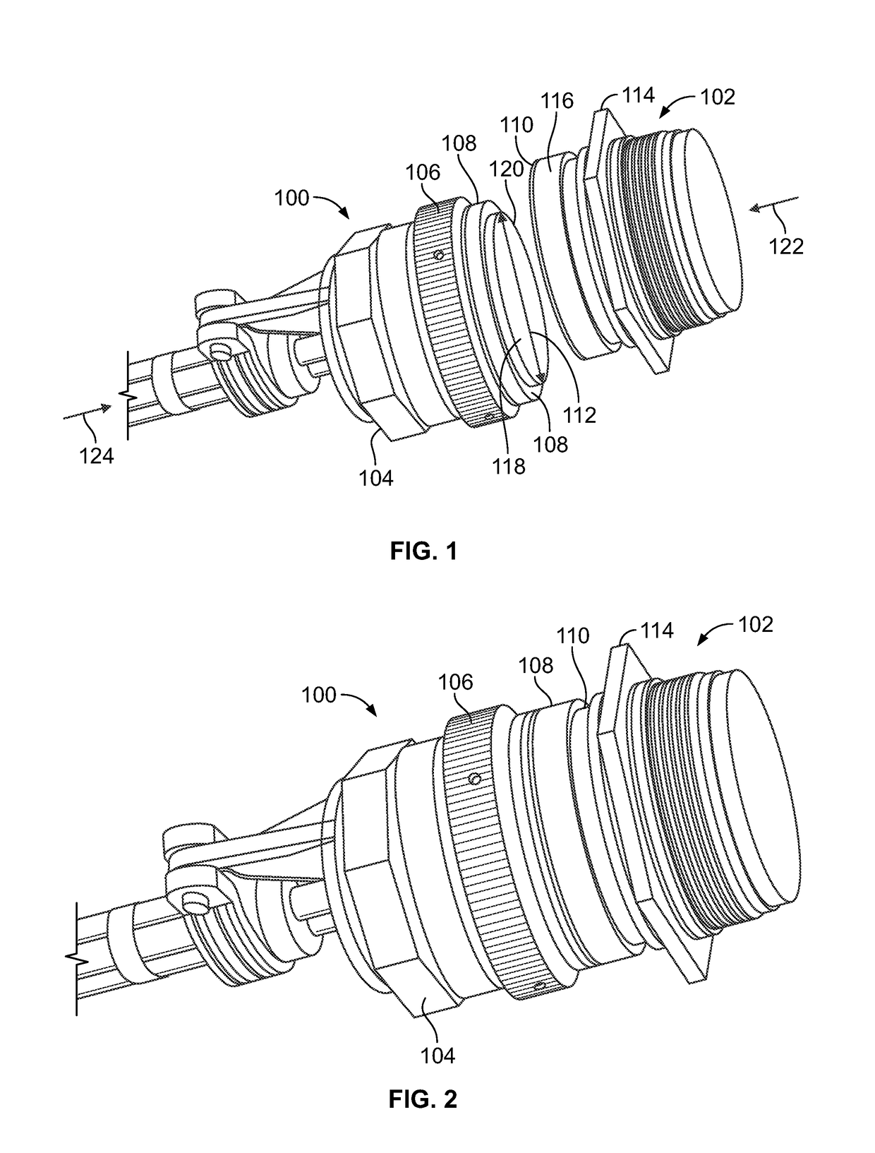
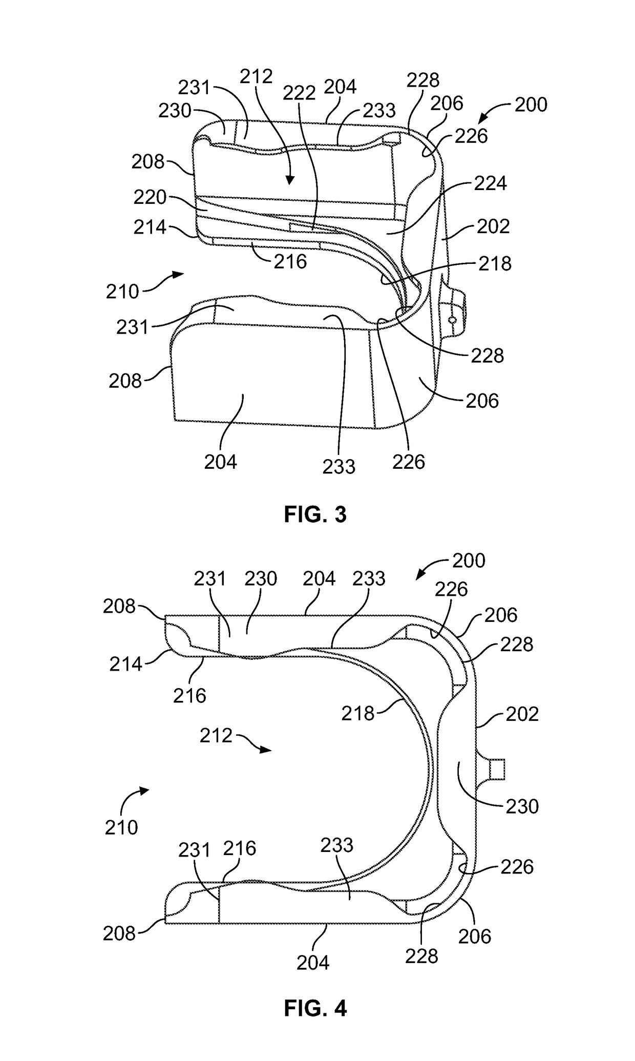
[0029]Certain embodiments of the present disclosure provide a retaining harness assembly that is configured to securely, safely, easily, and efficiently secure a first electrical connector, such as a test connector, to a second elect...


PUM


Abstract

An electrical system may include a first electrical connector configured to be coupled to an electrical panel, a second electrical connector configured to be coupled to a testing device that is configured to test components coupled to the electrical panel, and a retaining harness assembly that removably connects to the first and second electrical connectors to maintain a secure mating relationship between the first and second electrical connectors.

Description

FIELD OF THE DISCLOSURE[0001]Embodiments of the present disclosure generally relate to systems and methods for connecting electrical connectors together, and, more particularly, to systems and methods for securely connecting electrical connectors together with a retaining harness assembly.BACKGROUND OF THE DISCLOSURE[0002]Various components within a commercial aircraft are tested before the aircraft is delivered to a customer, and / or before and after flights. For example, a galley within a cabin of an aircraft may include various devices, or be in communication with systems and the like, that are electrically tested. A first electrical connector, such as a shipside connector, may be coupled to a main electrical board and / or power panel within the galley. A testing device may be configured to electrically couple to the first electrical connector through a second electrical connector, such as a test connector. The first and second electrical connectors may be removably connected toget...

Claims


Application Information

Patent Timeline
Patent Type & Authority Patents(United States)
IPC IPC(8): H01R13/62G01R1/04H01R13/64H01R13/502G01R31/00H01R13/639
CPCG01R1/0416G01R31/008H01R13/502H01R13/6395H01R13/6392H01R2201/26
Inventor DOWHOWER, THOMAS E.HAGA, HEATH W.HEINRICH, PETER M.PETERSON, RICKY M.
Owner THE BOEING CO
Why Eureka
Try Eureka