Work cart

a work cart and cart body technology, applied in the field of ergonomic devices, can solve the problems of prolonged working day in compromising and dangerously unsupported kneeling positions, overuse of the musculoskeletal system, and associated repetitive stress and pressure on many parts of the body

Active Publication Date: 2017-07-11
MANJARRES FR
View PDF48 Cites 4 Cited by
  • Summary
  • Abstract
  • Description
  • Claims
  • Application Information

AI Technical Summary

Benefits of technology

[0012]In other embodiments of the invention, the shin supports are secured to a rear base member of the cart with torsion mountings. In some embodiments, the torsion mountings allow the user to move the cart in a forward or reverse motion by alternately weighting and unweighting the proximal or knee ends of the shin supports while moving their legs in the direction of desired travel.

Problems solved by technology

Many industrial trades such as tile setting and grouting, concrete staining, wood floor refinishing, finish carpentry, electrical finishing, plumbing, and others, require workers to spend extended periods of the working day in compromising and dangerously unsupported kneeling positions.
Due to the nature of these jobs, there is associated repetitive stress and pressure on many parts of the body during the workday.
The prolonged and unsupported stress required to perform these duties can lead to musculoskeletal system overuse injuries.
These workers also spend a large amount of time bent over while kneeling.
Yet, cushioned kneepads only address one of the many stresses put on the body and do nothing to alleviate stress on the feet, ankles, hips, pelvis, and spine.
They ultimately do little to alleviate anything but moderate to severe knee pain and gross deformation of the knees.
All of these inventions, however, ultimately fall short of alleviating the compounding stressors on the worker's body that can ultimately lead to injury of the unsupported body part directly or indirectly by compensatory overuse.
Yet as before, even this apparatus fails to fully alleviate the pressures applied to the worker's knees, Achilles tendon and lower back while working.
Further, it does not facilitate stress-free movement around the work area, leading, in turn, to possible further injury.

Method used


Image

  • Work cart
  • Work cart
  • Work cart

Examples


Embodiment Construction

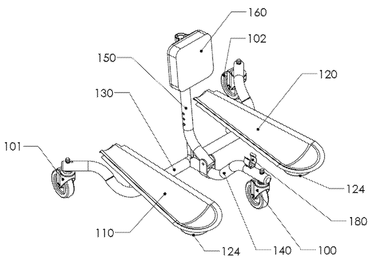
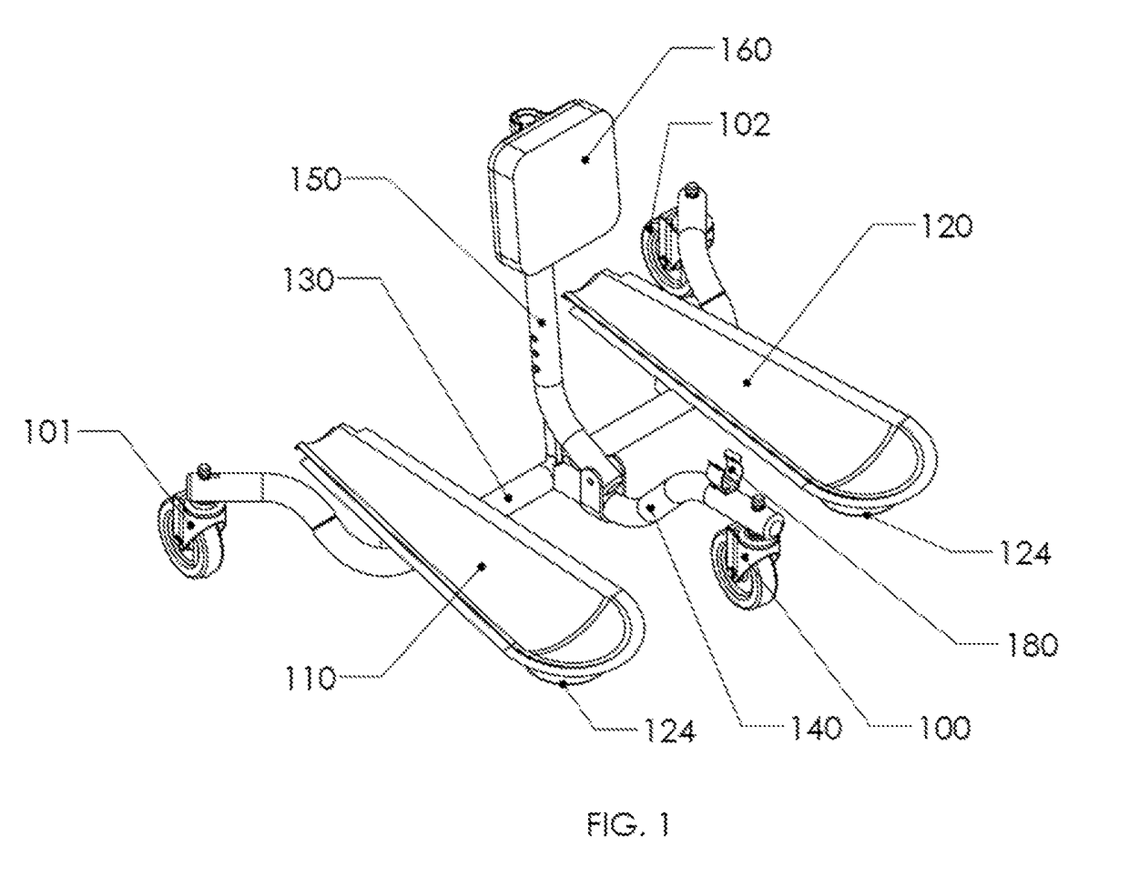
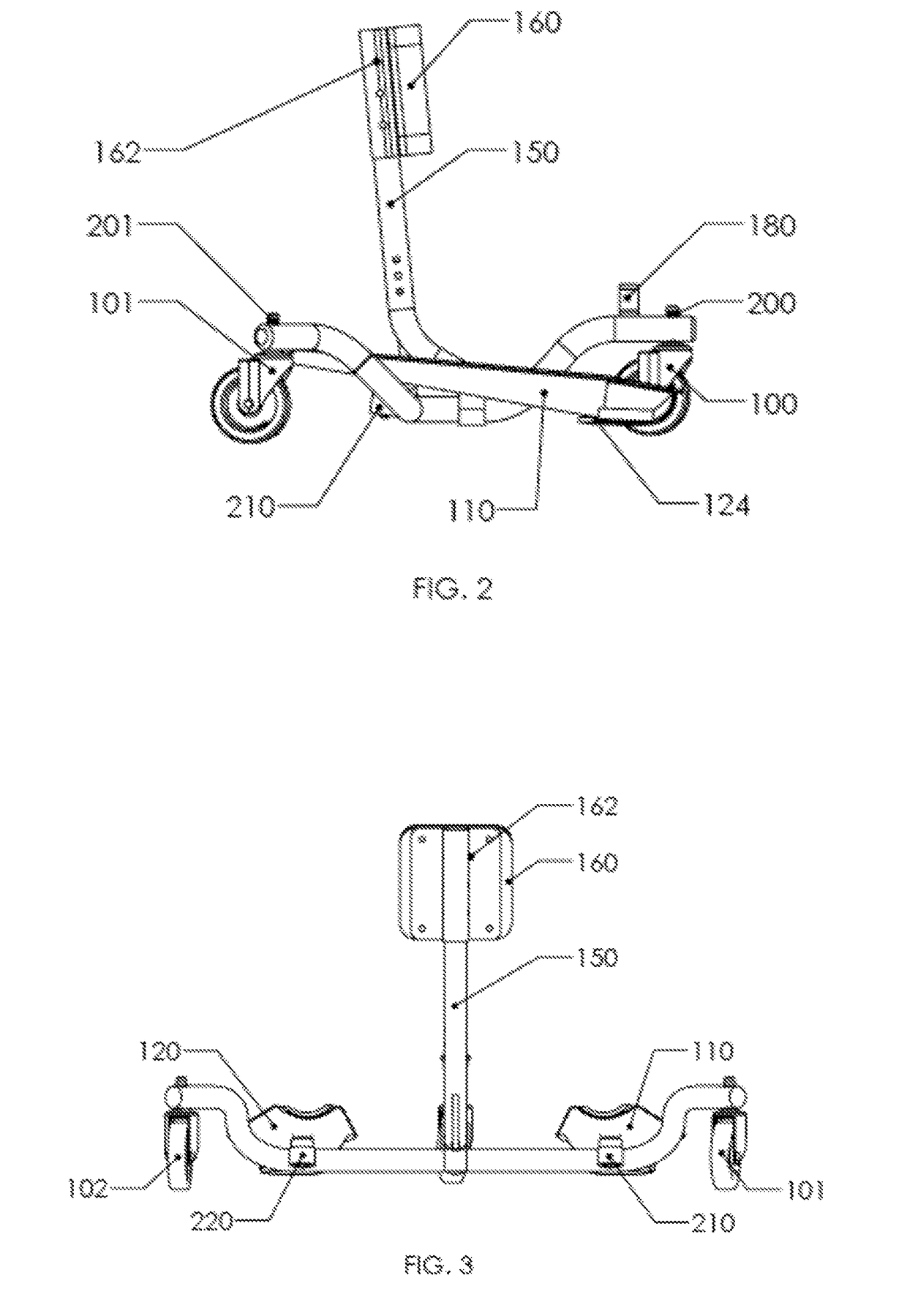
[0035]FIG. 1 shows an isometric view of an embodiment of the cart. In some embodiments the cart comprises a basic frame comprising a rear base member 130 with casters 101 and 102 attached to the proximal and distal ends, respectively, and a central base member 140 attached perpendicularly to the rear base member 130 at the central portion of the rear base member 130. As is well known in the art, casters comprise wheels, a frame and axle to hold the wheel, and a mounting pin to facilitate swivel motion. The central base member 140 has a front caster 100 at the proximal end. A back support member 150 is attached to the central portion of the central base member 140 and extends in a substantially vertical direction therefrom. The back support member 150 further comprises a padded back support element 160 attached thereto. There are two shin supports 110 and 120 pivotably mounted on the rear base member 130. The back support member 150 may be hingeably attached to the central base membe...


PUM


Abstract

The invention comprises a cart for reducing and alleviating ergonomic stresses on the musculoskeletal system of workers in a variety of building trades, including tile setting and grouting, concrete staining, wood floor refinishing, finish carpentry, electrical finishing, plumbing, and others, that require workers to spend extended periods of the working day in compromising and unsupported kneeling positions. The cart is designed to distribute forces along the shinbone of the worker and redirect them from the back, pelvis, keens, ankles and other joints. A further advantage of the cart is the ability to maneuver around the work surface using pivoting shin supports and without the need for repeated standing and kneeling.

Description

CROSS-REFERENCE TO RELATED APPLICATIONS[0001]This application is a continuation of PCT / US2014 / 023255 filed Mar. 11, 2014 which claims priority from U.S. Provisional Application 61 / 778,371 filed Mar. 12, 2013, the disclosures of which are hereby incorporated by reference in their entireties for all purposes.FIELD OF THE INVENTION[0002]The present invention is in the area of ergonomic apparatus to reduce and relieve stress on the musculoskeletal system, and to decrease overuse injuries to the joints, tendons and muscles of the feet, ankles, knees, sacral spine, lumbar spine, thoracic spine and cervical spine of workers who are required to spend extended time in a kneeling or squatting position.BACKGROUND OF THE INVENTION[0003]Many industrial trades such as tile setting and grouting, concrete staining, wood floor refinishing, finish carpentry, electrical finishing, plumbing, and others, require workers to spend extended periods of the working day in compromising and dangerously unsuppo...

Claims


Application Information

Patent Timeline
Patent Type & Authority Patents(United States)
IPC IPC(8): B25H5/00A01B75/00A47C9/02
CPCB25H5/00A01B75/00A47C9/027
Inventor MANJARRES, FRANK
Owner MANJARRES FR
Why Eureka
Try Eureka