
Sterilization treatment line and cleaning method thereof

a technology of sterilization treatment and cleaning method, which is applied in the direction of food thermal treatment, cleaning process and apparatus, packaging, etc., can solve the problems of large system size, high installation cost, and high time consumption of cip treatment, sip treatment and similar treatment, so as to shorten the cip treatment time and improve the cleaning effect. , the effect of low cleaning function

Active Publication Date: 2017-07-18
DAI NIPPON PRINTING CO LTD
View PDF34 Cites 6 Cited by
  • Summary
  • Abstract
  • Description
  • Claims
  • Application Information

AI Technical Summary

Benefits of technology

The present invention provides a more efficient and compact sterilization treatment line for product liquid. It achieves this by using a smaller number of parallel intermediate piping lines for products that are prone to burning. This reduces the amount of chemical liquid required, saving money. The intermediate piping lines can also be easily cleaned during production, allowing for the use of less expensive chemical agents for longer periods of cleaning. Overall, this reduces the time and cost of sterilizing product liquids.

Problems solved by technology

However, the above arrangement of the piping lines requires a wide installation space and excessive cost, and accordingly, if such piping lines are provided in two lines, the sterilization system is itself made large in size and extremely increase a system installation cost.
Moreover, the CIP treatment, SIP treatment and like treatment require much time, increased amount of chemical liquid to be used, and a lot of energy to be utilized.
Furthermore, since the intermediate piping lines can be cleansed during the production and filling of the product liquid, it is not necessary to use an expensive chemical agent having high cleaning function for shortening the CIP treatment time, and it is possible to use a cheap chemical agent having relatively low cleaning function a relatively long time for cleaning.

Method used


Image

  • Sterilization treatment line and cleaning method thereof
  • Sterilization treatment line and cleaning method thereof
  • Sterilization treatment line and cleaning method thereof

Examples


Embodiment Construction

[0033]Hereunder, modes for embodying the present invention will be explained with reference to the accompanying drawings.

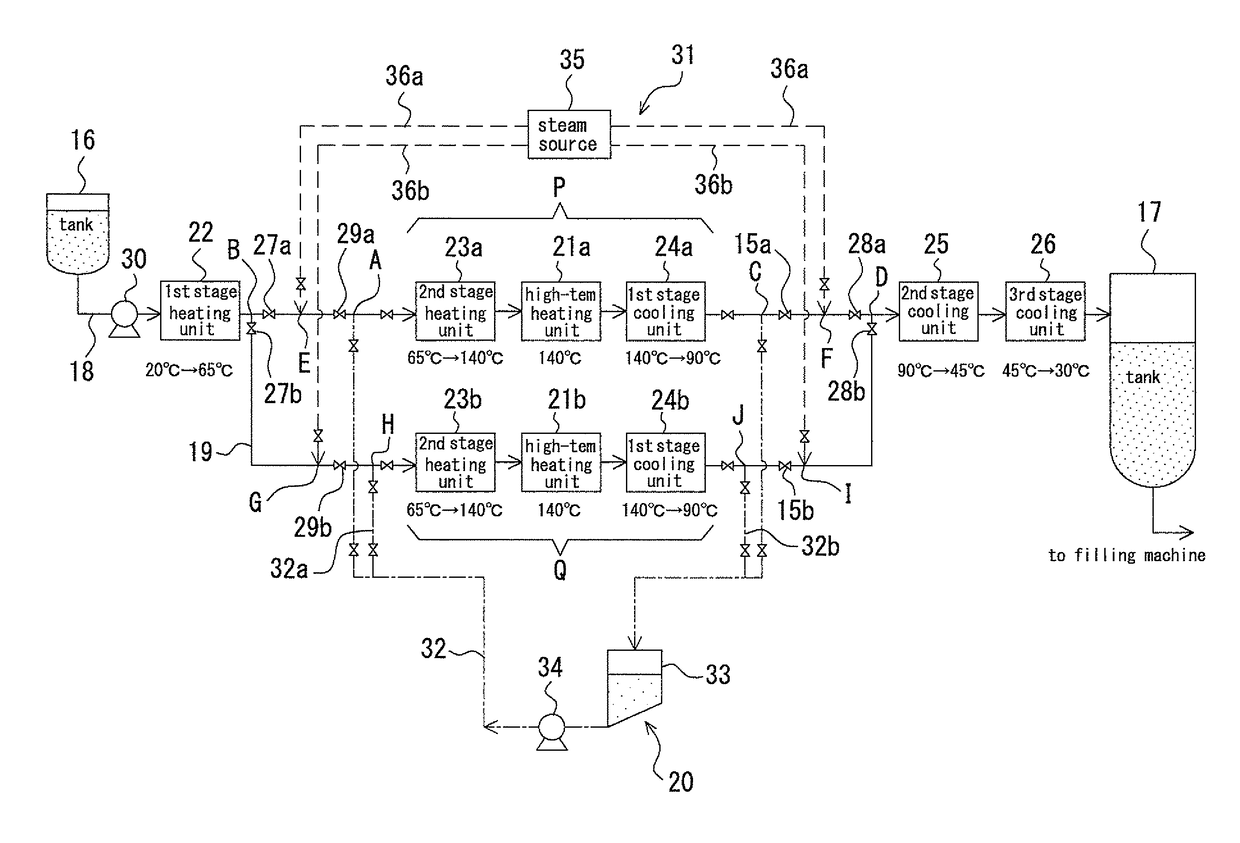
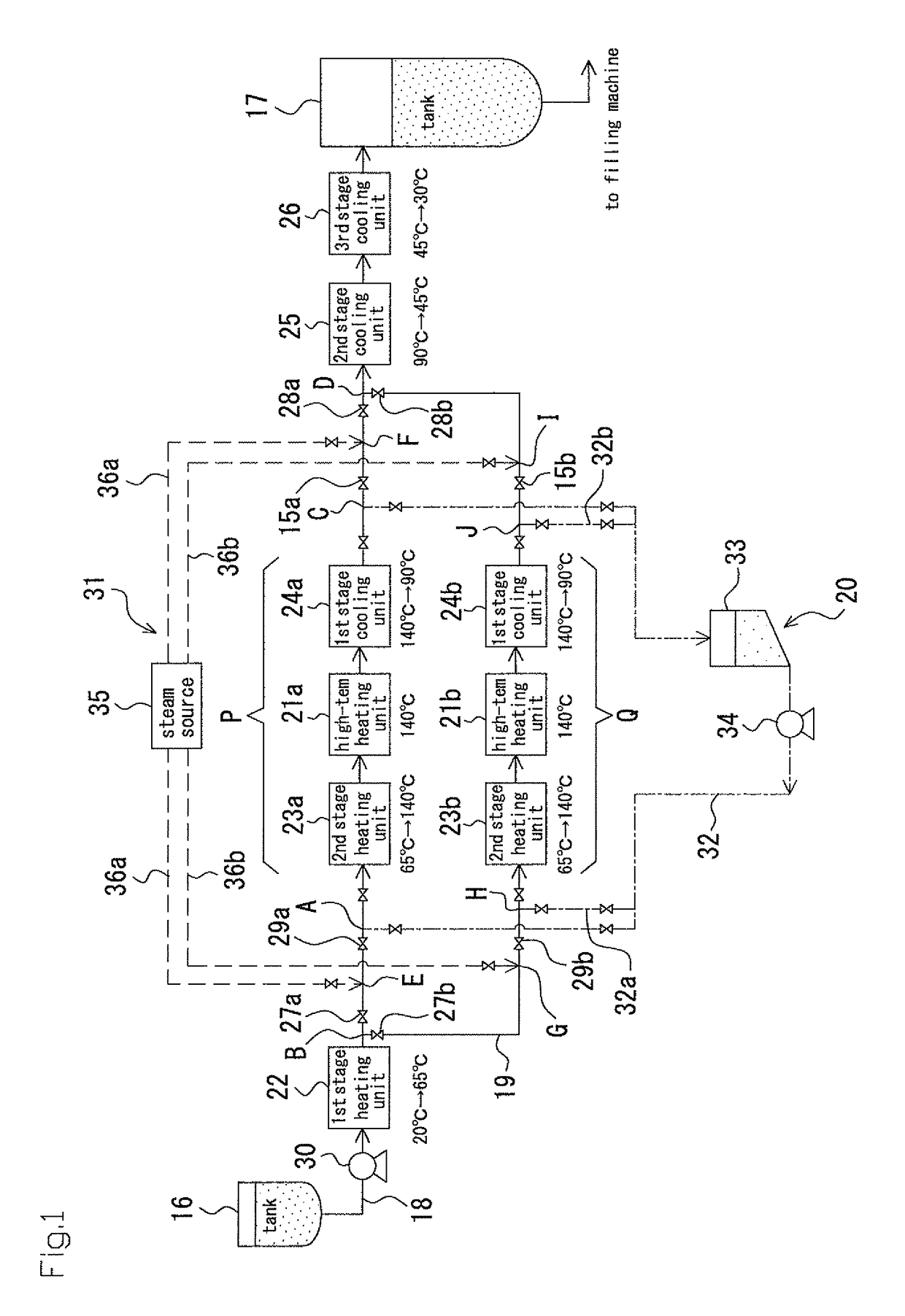
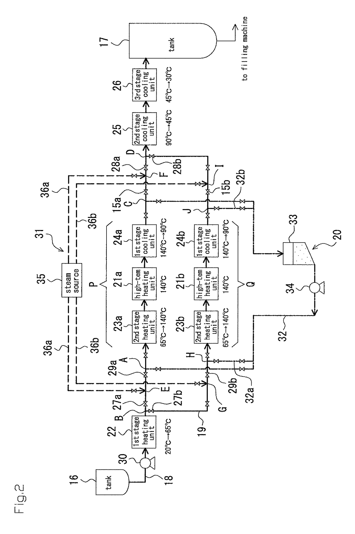
[0034]A sterilization treatment line such as shown in FIG. 1 is installed in a piping line of an aseptic filling system treating a large volume of product liquid such as drink.

[0035]With reference to FIG. 1, reference numeral 16 denotes an upstream side tank for storing a product liquid such as drink prepared but not sterilized, and reference numeral 17 denotes a downstream side tank for once storing the sterilized product liquid and then supplying it to a filling machine, not shown.

[0036]The respective upstream side tank 16 and downstream side tank 17 are capable of storing a large volume of product liquid, and for example, it is possible to store several tons or ten-and-several tons of product liquid. Further, in the upstream side tank 16, the product liquid before the sterilization treatment is stored at a normal temperature of, for example, about 20° C., and o...


PUM


Abstract

Provided is a sterilization processing line resulting from an upstream tank (16) and a downstream tank (17) that each retain a product liquid being connected by a duct (18) that transfers the product liquid, a high-temperature heating unit (21) that sterilizes the product liquid being provided to the intermediate section of the duct, one or a plurality of stages of heating units (22, 23) that heat the product liquid in stages being provided to the duct reaching from the upstream tank to the high-temperature heating unit, and one or a plurality of stages of cooling units (24, 25, 26) that cool the product liquid in stages being provided to the duct reaching from the high-temperature processing unit to the downstream tank. A plurality of parallel intermediate duct systems (P, Q) are provided at the interval from the heating unit (23) at the stage that is in a temperature range at which burning to the product liquid can occur to the cooling unit (24) at the stage that similarly is in the temperature range at which burning to the product liquid can occur, and the sterilization processing and the CIP and positive pressure holding processing of the product liquid transferred from the upstream tank to the downstream tank are performed switching between the parallel plurality of intermediate duct systems.

Description

TECHNICAL FIELD[0001]The present invention relates to a line for performing sterilization treatment to product liquid such as drink and a method of cleaning the sterilization treatment line.BACKGROUND TECHNOLOGY[0002]Conventionally, to a piping line or arrangement in an aseptic filling system for drink or like, in order to remove dirt or bacteria adhering to an inside of a conduit, a CIP (Cleaning In Place) treatment and SIP (Sterilization In Place) treatment are performed (for example, refer to Patent Document 1, paragraph [0003]).[0003]The CIP treatment is performed, for example, by adding alkaline cleaner such as caustic soda or acidic cleanser to water and circulating such water through a fluid food filling path. According to such treatment, dirt such as remaining material or like adhering to the fluid food filling path can be removed (for example, refer to Patent Documents 1, 2, and 3).[0004]The SIP treatment is performed, for example, by circulating steam or heated water throu...

Claims


Application Information

Patent Timeline
Patent Type & Authority Patents(United States)
IPC IPC(8): A23L3/00B08B9/027A23L2/46B65B55/14A23L3/18
CPCA23L3/001A23L2/46A23L3/18B08B9/027B65B55/14B65B2210/06A23V2002/00A23V2300/24
Inventor HAYAKAWA, ATSUSHI
Owner DAI NIPPON PRINTING CO LTD
Features
  • Generate Ideas
  • Intellectual Property
  • Life Sciences
  • Materials
  • Tech Scout
  • Unparalleled Data Quality
  • Higher Quality Content
  • 60% Fewer Hallucinations
Learn More