
Final position locking feature of multi-turn rotational device having an axially translating wheel or a clocked lock passage gear

a technology of axial translation wheel and locking feature, which is applied in the direction of valve details, valve arrangement, thin material handling, etc., can solve the problem of not concluding that the final position of the multi-turn mechanism has been achieved, and achieve the effect of simple mechanical solutions and cost prohibitiv

Active Publication Date: 2017-07-18
ITT MFG ENTERPRISES LLC
View PDF18 Cites 3 Cited by
  • Summary
  • Abstract
  • Description
  • Claims
  • Application Information

AI Technical Summary

Benefits of technology

The present invention provides a mechanical solution for ensuring that a multi-turn mechanism is fully engaged, which prevents further rotation until the mechanism is pulled. This solution is simpler and more cost-effective than electronic solutions, making it ideal for applications where there is no ready electrical power.

Problems solved by technology

One disadvantage of the prior art technique shown in FIG. 1 is that there is not a conclusive indication that a final position of a multi-turn mechanism has been achieved when using a simple spring-pin ratchet mechanism.

Method used


Image

  • Final position locking feature of multi-turn rotational device having an axially translating wheel or a clocked lock passage gear
  • Final position locking feature of multi-turn rotational device having an axially translating wheel or a clocked lock passage gear
  • Final position locking feature of multi-turn rotational device having an axially translating wheel or a clocked lock passage gear

Examples


Embodiment Construction

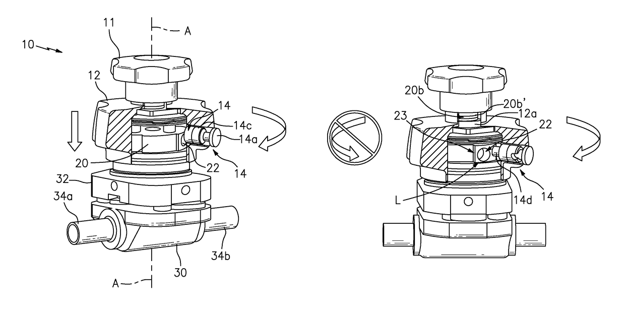
[0034]FIGS. 2 and 3 show the present invention in the form of apparatus generally indicated as 10, 10′. By way of example, the apparatus 10, 10′ is shown in the form of a valve also indicated 10, including a diaphragm valve, featuring a cover 12 in combination with at least one inner housing component generally indicated as 20, 20′.

[0035]The cover 12 may be configured with a biased-pin 14 generally indicated as mounted therein. In particular, the biased-pin 14 may include, or take the form of a spring-pin, e.g., having a combination of a pin 14a, a biasing member 14b, a head 14c and an end portion 14d. The biasing member 14b may be configured to urge the pin 14a inwardly towards the at least one inner component 20, 20′. The biasing member 14b may include, or take the form of, a spring or elastomeric material configured to be resilient and move by elastic force. The biased-pin 14 shown in FIGS. 2-3 is shown by way of example, and the scope of the invention is intended to include othe...


PUM


Abstract

A valve, including a diaphragm valve, is provided featuring a cover in combination with at least one inner housing component. The cover may be configured with a biased-pin mounted therein. The at least one inner housing component may be configured with a hole or slot formed at a predetermined location where the biased-pin is at when the valve is calibrated to be at a final position. The cover may be configured to rotate and cause an axial translation between the cover and the at least one inner housing component so that the biased-pin engages the hole or slot when the valve is at the final position so as to stop any further axial and rotational movement.

Description

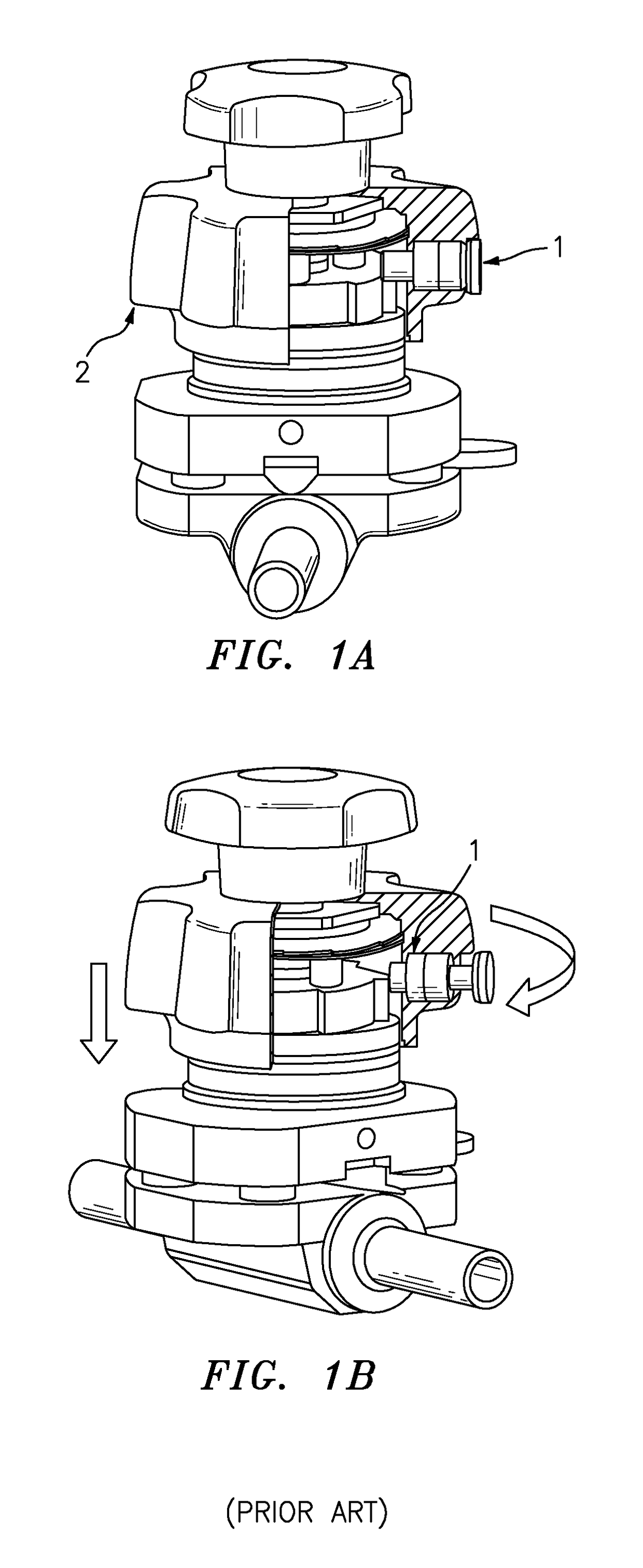
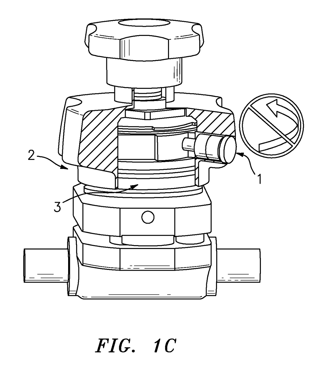
BACKGROUND OF THE INVENTION[0001]1. Field of the Invention[0002]The present invention relates to a diaphragm valve; and more particularly relates to a weir-type diaphragm valve.[0003]2. Brief Description of Related Art[0004]FIG. 1 shows an example of a typical locking mechanism for a rotating system in the form of a spring-pin ratchet. In this example, the spring-pin ratchet has a rotating cover which moves along an axis of rotation, however, an axial translation is not required for the spring-pin ratchet mechanism to work. In FIG. 1A, the spring-pin ratchet has a spring-pin 1 fully engaged into a trough between teeth that form part of the ratcheting mechanism. Note that although the spring-pin 1 appears to be seated, the cover 2 has not been tightened. During the rotation, the spring-pin 1 rides over individual teeth, as shown in FIG. 1B. When fully tightened, the spring-pin 1 is flush; however the passive visual indication 3 for this system is the covering of the decal by the axia...

Claims


Application Information

Patent Timeline
Patent Type & Authority Patents(United States)
IPC IPC(8): F16K35/02F16K37/00
CPCF16K37/0008F16K35/025F16K35/027Y10T137/8275
Inventor MATALON, LOUIS E.HAUN, STEVENYODER, MICHAEL D.
Owner ITT MFG ENTERPRISES LLC
Learn More