
Filter press

a filter press and press body technology, applied in the field of filter presses, can solve the problems of large area of the closing cylinder piston rod exposed to contamination, short cycle time, and limited press volume, and achieve the effect of improving protection

Active Publication Date: 2013-08-20
ANDRITZ TECH & ASSET MANAGEMENT
View PDF14 Cites 3 Cited by
  • Summary
  • Abstract
  • Description
  • Claims
  • Application Information

AI Technical Summary

Benefits of technology

The invention is a filter press that allows for rapid opening and closing of the filter plates, while still providing enough closing pressure for the filter plate assembly. It also improves protection against contamination of mechanical components and equipment for opening and closing the filter plate assembly. The filter press achieves this through a sliding carriage and hydraulic drive for the pressing device, as well as recesses for additional press rolls to prevent bending of the side beams during the filtering process.

Problems solved by technology

In some applications, for example in mining, the cycle times are very short, which means that closing of the filter plate assembly, filling with the suspension to be filtered, the filtration process itself, opening of the filter plate assembly, discharge of the filter cake, and washing of the filter cloths all have to proceed relatively quickly, often within a few minutes.
If the closing cylinder is used, for example, the press volume is limited because only one limited cylinder stroke can be realized.
A long cylinder stroke also necessitates large quantities of oil and exposes large areas of the closing cylinder piston rod to contamination from falling filter cake.
In addition, there are also disadvantages from radial forces and other unfavourable loads on the piston rod, the piston, and the respective seals.
Lastly, opening and closing the filter plate assembly using the closing cylinder takes considerable time because the closing cylinder is designed for high closing pressure, but not for rapid piston movement.
The correspondingly thin piston rods, however, cause problems due to their low mechanical loading capacity, and it is often necessary to use several additional hydraulic drives of this kind, which have to be controlled exactly however, in order to ensure synchronous movement.
Ultimately, these systems also do not solve the problem of long piston rods and their being contaminated by falling filter cake.

Method used


Image

  • Filter press
  • Filter press
  • Filter press

Examples


Embodiment Construction

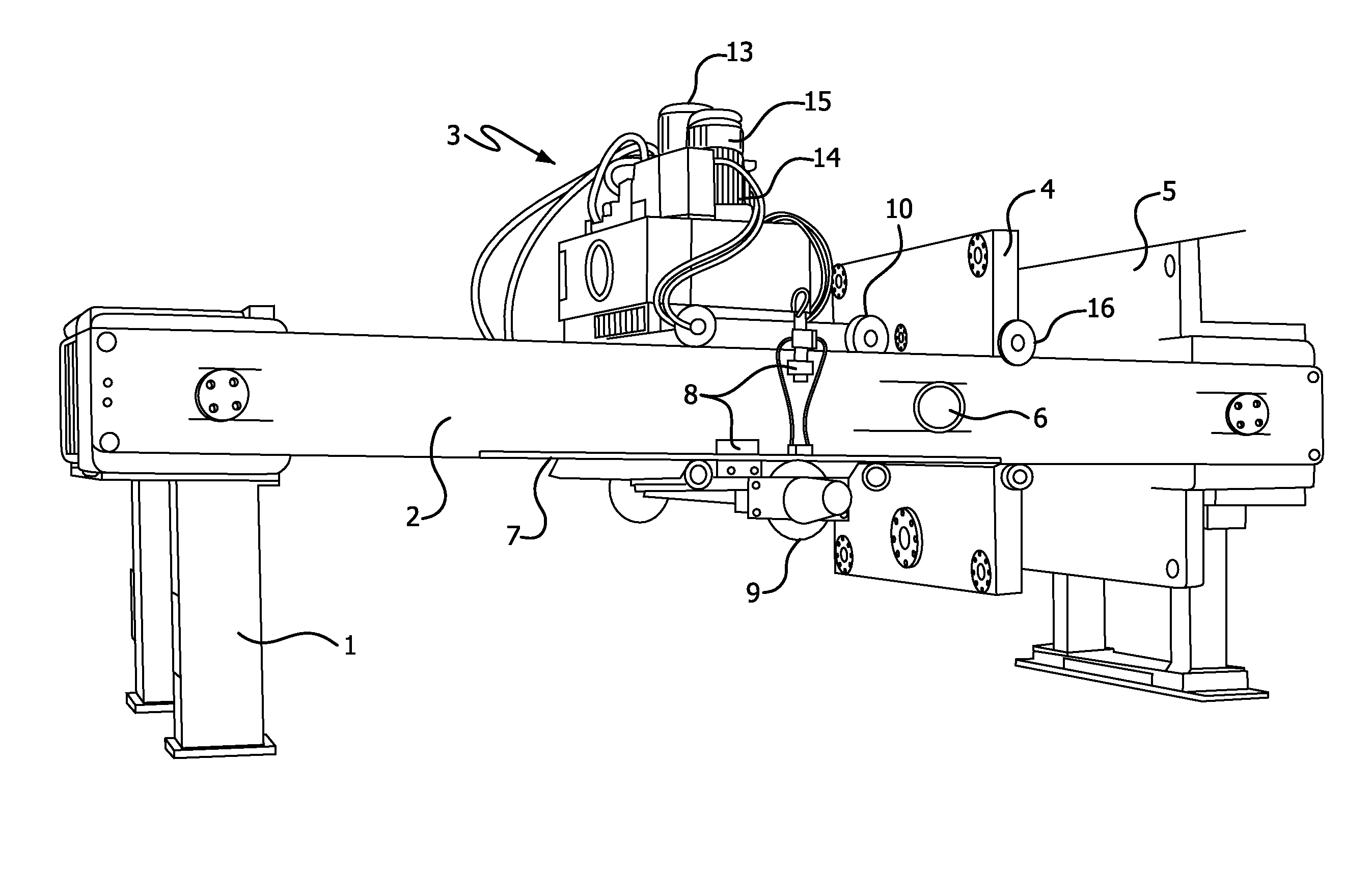
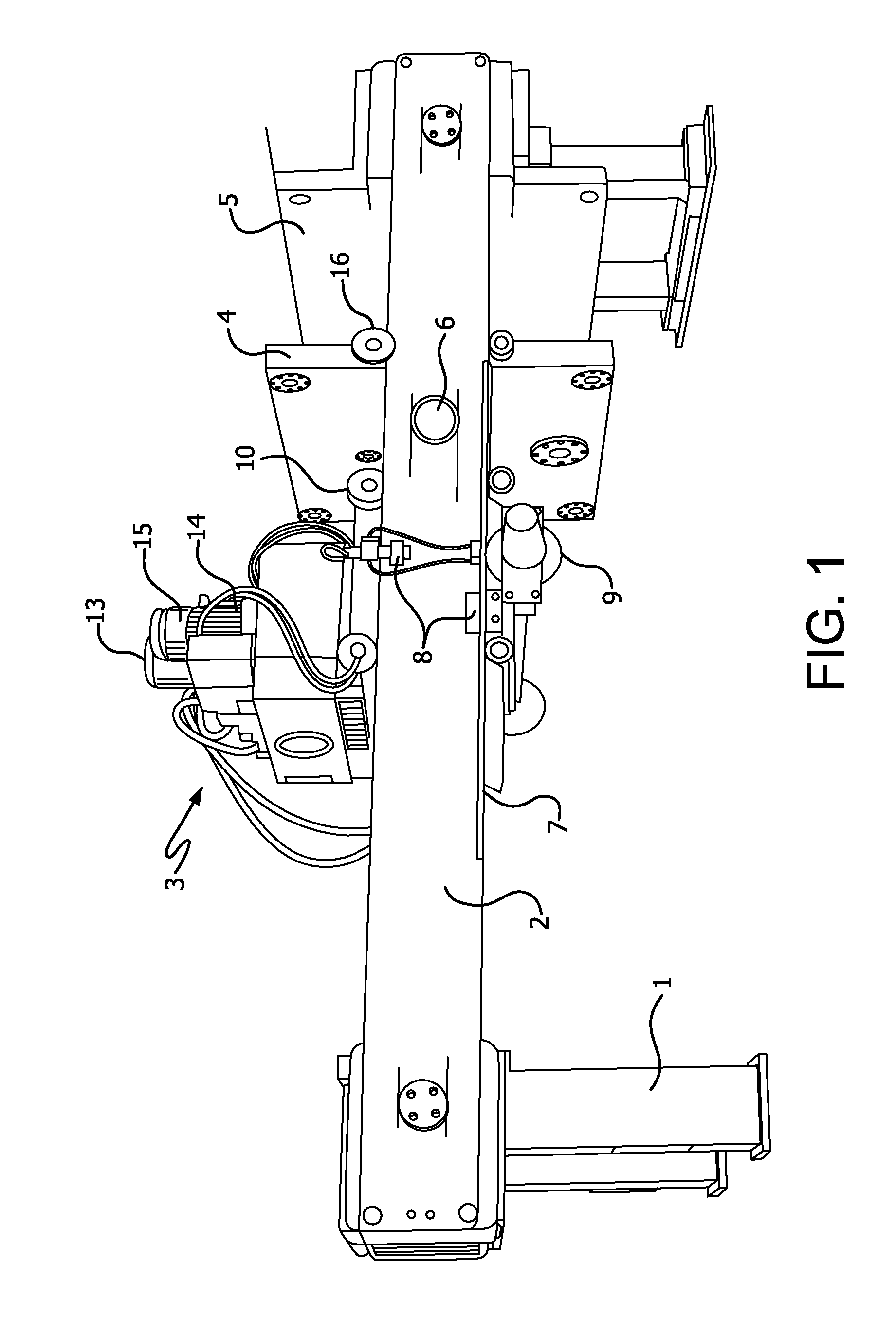
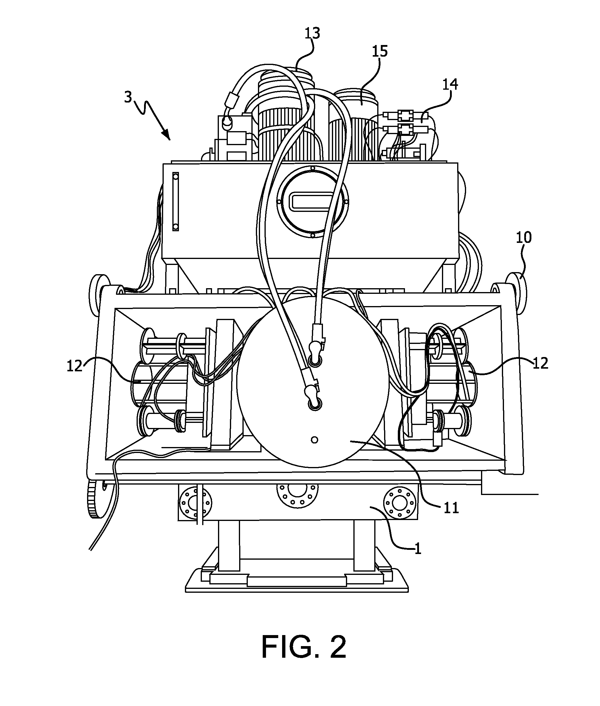
[0018]FIG. 1 shows a perspective view of an embodiment of a filter press according to the invention, with a press frame containing end columns 1, side beams 2, as well as a header 5 at the end of the side beams 2, where the header 5 serves in particular to absorb the pressing and tensile forces occurring during manipulation of the filter plate assembly 18. In addition, there is a pressure plate 4 mounted in a movable support running along the longitudinal axis of the side beams 2 with the aid of supporting rollers 16. The filter plate assembly 18, which is not shown in FIGS. 1-3 and in FIG. 6, is located between the pressure plate 4 and the header 5. The supply lines required for filtration in order to feed in the suspension to be filtered and carry away the filtrate are laid through the header 5.

[0019]According to the invention there is also a sliding carriage 3 on the side beams 2, which is carried on guide rollers 10. The sliding carriage 3 can be moved along the longitudinal axi...


PUM

PropertyMeasurementUnit
Angleaaaaaaaaaa

Abstract

A filter press includes a press frame containing side beams (2) to support filter plates (17) movably along the longitudinal axis of the side beams (2). The filter plates (17) are oriented at right angles to the longitudinal axis of the side beams (2) and connected to one another. A pressure plate (4) can be moved along the longitudinal axis of the side beams (2) by a pushing or pulling device, and which presses the filter plates of the sliding carriage (3) against one another during the filtration process. The pushing or pulling device is mounted on a sliding carriage (3) that can be moved on the side beams (2) along the longitudinal axis of the side beams (2) by a drive unit mounted on the sliding carriage (3).

Description

BACKGROUND OF THE INVENTION[0001]The invention relates to a filter press with a press frame to support filter plates movably along the longitudinal axis of the press frame, where the filter plates are oriented at right angles to the longitudinal axis of the press frame and connected to one another, and where a pressure plate is provided that can be moved along the longitudinal axis of the press frame by means of pushing or pulling equipment and which presses the filter plates against one another during the filtration process.[0002]Filter presses of this kind are used to separate solids from the liquid phase of a suspension to be filtered. This filtration process takes place in the filter plates, where several filter plates are joined to one another to form a filter plate assembly. With the aid of a closing cylinder, usually a hydraulic closing cylinder, pressure is applied to the filter plate assembly in order to guarantee the necessary leak-tightness between the individual filter p...

Claims


Application Information

Patent Timeline
IPC IPC(8): B01D25/19B01D25/12
CPCB01D25/19
Inventor PASCHEDAG, THOMASBOHME, MARION
Owner ANDRITZ TECH & ASSET MANAGEMENT
Learn More