Wing tip device having configurations for flight and ground-based operations

a technology of wing tip device and configuration, applied in the field of aircraft, can solve the problem of limited length of downwardly extending (anhedral) wing tip device, and achieve the effect of increasing the ground clearance of the wing tip devi

Active Publication Date: 2017-07-25
AIRBUS OPERATIONS LTD
View PDF38 Cites 6 Cited by
  • Summary
  • Abstract
  • Description
  • Claims
  • Application Information

AI Technical Summary

Benefits of technology

[0006](ii) a ground-operating configuration in which the wing tip device extends rearwardly such that the ground clearance of the wing tip device is increased and the effective span of the wing is decreased. The present invention therefore allows a relatively long downwardly extending wing tip device to be used during flight, but for the ground clearance to then be increased during operations on the ground to adhere to airport clearance rules.
[0017](ii) a ground-operating configuration in which the moveable region extends rearwardly such that the ground clearance of the wing tip device is increased. The present invention therefore allows a relatively long downwardly extending wing tip device to be used during flight without violating airport ground clearance rules (when the wing tip device is configured in the ground-operating configuration).
[0025]The end of the wing may comprise a second wing tip device. The second wing tip device may extend upwardly above the wing. The first wing tip device (when in the high-altitude cruise configuration) is preferably arranged to counteract the vorticity from the second, upwardly extending, wing tip device. Thus, embodiments of the invention in which the wing has both the downwardly extending wing tip device, and an upwardly extending wing tip device, may have relatively low induced drag (without being unduly limited by the presence of the downwardly extending device by airport clearance rules).
[0029]The wing is preferably a dihedral wing. The present invention is especially attractive for dihedral wings because a downwardly extending wing tip device on a dihedral wing may offset, to at least some degree, any loss in effective span when the dihedral wing bends upwards during flight. In the high-altitude cruise configuration, the wing tip device may be higher than the lowest point of the air vehicle fuselage.
[0035]for ground-based operations, configuring the wing tip device in a ground-operating configuration, in which ground-operating configuration the wing tip device rearwardly extends behind the wing to increase the ground clearance of the wing tip device.

Problems solved by technology

It can be desirable to have relatively long wing tip devices, but the length of downwardly extending (anhedral) wing tip devices tends to be limited by airport operating rules which govern various clearances required when maneuvering around the airport (such as the span and / or ground clearance required for gate entry and safe taxiway usage).

Method used


Image

  • Wing tip device having configurations for flight and ground-based operations
  • Wing tip device having configurations for flight and ground-based operations
  • Wing tip device having configurations for flight and ground-based operations

Examples


first embodiment

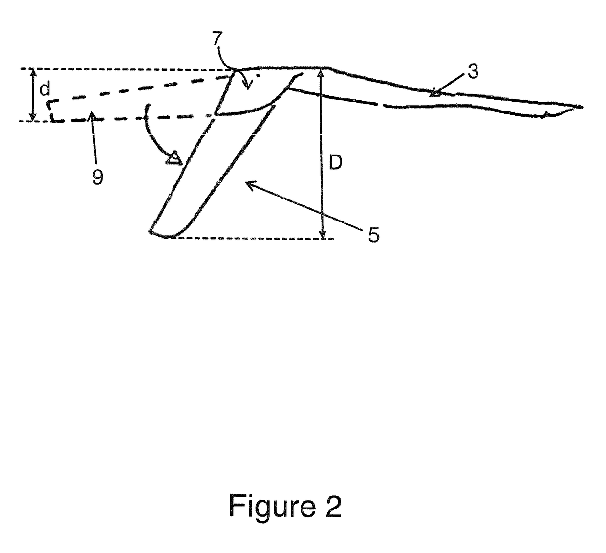
[0053]FIGS. 2, 3 and 4 show the wing tip device on the aircraft of the invention from end, plan and front elevations respectively. For the sake of clarity, the effective span increase s, created by the wing tip device, is exaggerated in the plan view of FIG. 3.

[0054]The wing tip device 5 is formed of a fixed region 7 adjoining the aircraft wing 3, and a moveable region 9. A thin extension element (not shown) on the moveable region 9 overlaps the underside of the fixed region 7. The moveable region 9 is rotatably mounted on the fixed region 7 about an axis of rotation 11 (see FIG. 4) that passes through the overlap.

[0055]In FIG. 2, the structure defining the moveable region 9 is drawn as a continuous line to show the wing tip device 5 in a high-altitude cruise configuration, and is drawn as a dashed line to show the wing tip device 5 in a ground-operating configuration (described in more detail below). In FIG. 4, the rotatable region 9 is drawn as a dashed line to show the wing tip d...

second embodiment

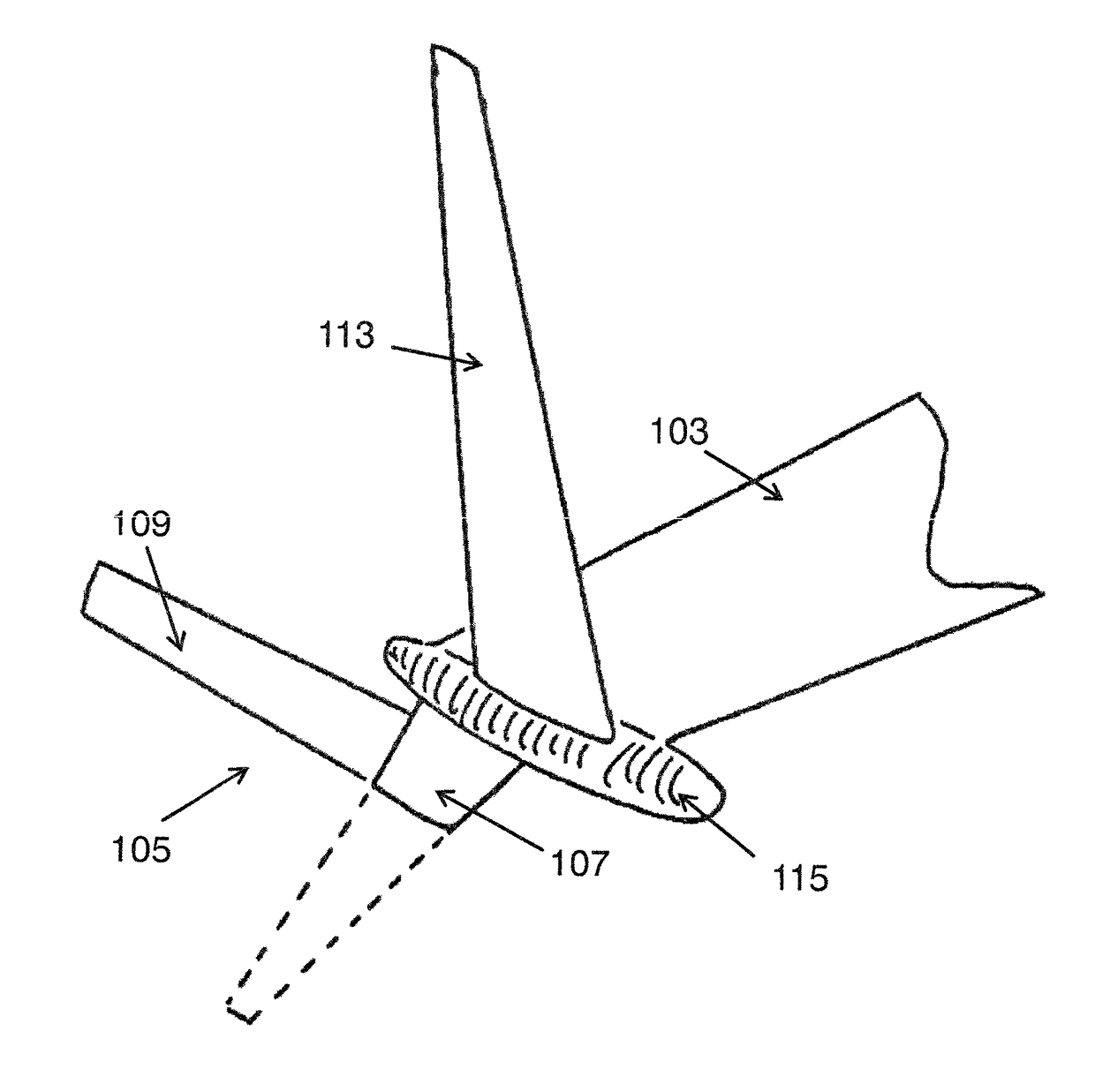
[0061]FIGS. 8 and 9 are front views of wing tip devices according to other embodiments of the invention. In the embodiment of FIG. 8, the reference numbers are 200 series numbers and each correspond to a respective one of the 100 series numbers shown in FIGS. 5 to 7. For example, the end of a wing is designated by reference number 203 in FIG. 8 and designated by 103 in FIG. 5. In FIG. 8, the upwardly extending wing tip device 213 is fixed at a lower cant than the invention, and the bulbous body 215 protrudes further on the lower side of the wing 203 than the upper side. In the embodiment of FIG. 9, the reference numbers are 300 series numbers and each correspond to the 100 series numbers shown in FIGS. 5 to 7. For example, the end of a wing is designated by reference number 303 in FIG. 9 and designated by 103 in FIG. 5. The bulbous region 315 is located adjacent the root of the fixed region 307 of the downwardly extending device 305, but does not extend all the way to the leading ed...


PUM


Abstract

An aircraft including a wing, the end of the wing having a wing tip device, wherein the wing tip device includes a moveable region that is rotatable, about an axis of rotation extending out of the plane of the wing tip device, between: (i) a high-altitude cruise configuration in which the moveable region extends downwardly below the wing; and (ii) a ground-operating configuration in which the moveable region extends rearwardly behind the wing such that the ground clearance of the wing tip device is increased.

Description

RELATED APPLICATIONS[0001]This application is the U.S. national phase of International Application No. PCT / GB2014 / 050166 filed 22 Jan. 2014 which designated the U.S. and claims priority to GB 1301680.3 filed 31 Jan. 2013, the entire contents of each of which applications are hereby incorporated by reference.TECHNICAL FIELD[0002]The present invention relates to an aircraft having a downwardly extending wing tip device, and to a method of configuring the wing tip device.BACKGROUND OF THE INVENTION[0003]The use of wing tip devices, such as winglets, on aircraft is well known. Such devices seek to improve the aerodynamic performance of the aircraft, typically reducing induced drag and increasing lift. It can be desirable to have relatively long wing tip devices, but the length of downwardly extending (anhedral) wing tip devices tends to be limited by airport operating rules which govern various clearances required when maneuvering around the airport (such as the span and / or ground clear...

Claims


Application Information

Patent Timeline
Patent Type & Authority Patents(United States)
IPC IPC(8): B64C23/06B64C3/56B64C5/08
CPCB64C3/56B64C5/08B64C23/065Y02T50/164B64C23/076Y02T50/10
Inventor BRADSHAW, PHILIP JOHN TEMPLETONWHITEHOUSE, IAN ROYWOOD, NORMANALEXANDER, STUARTRANDALL, JOHN DAVID
Owner AIRBUS OPERATIONS LTD
Why Eureka
Try Eureka