Pedal device for electronic percussion instrument

a technology of electronic percussion and pedal device, which is applied in the direction of instruments, electrophonic musical instruments, musical instruments, etc., can solve the problems of low detection accuracy of the first sensor with respect to the rotation of the foot board, and achieve the effect of accurate detection, easy application, and shearing force applied on the second pressed par

Active Publication Date: 2017-08-01
ROLAND CORP
View PDF22 Cites 1 Cited by
  • Summary
  • Abstract
  • Description
  • Claims
  • Application Information

AI Technical Summary

Benefits of technology

[0012]Besides, one longitudinal end side of the pedal is rotatably and pivotally supported by the base. A pressing part is formed at the other longitudinal end side of the pedal. That is, the pressing part is disposed away from a rotation shaft of the pedal. The above configuration ensures a large displacement range when the pressing part displaces with the rotation of the pedal. Furthermore, the first detection means disposed on a first portion or the second detection means disposed on a second portion is disposed on a displacement trajectory of the pressing part. Thus, the electronic percussion instrument including the first detection means and the electronic percussion instrument including the second detection means can both detect the rotation of the pedal accurately.
[0026]The invention further provides a base of a pedal device for an electronic percussion instrument, which is capable of accurately detecting rotation of a pedal and achieves part commonality.

Problems solved by technology

As a result, compared with the second sensor, the first sensor has low detection accuracy with respect to the rotation of the foot board.

Method used


Image

  • Pedal device for electronic percussion instrument
  • Pedal device for electronic percussion instrument
  • Pedal device for electronic percussion instrument

Examples


Embodiment Construction

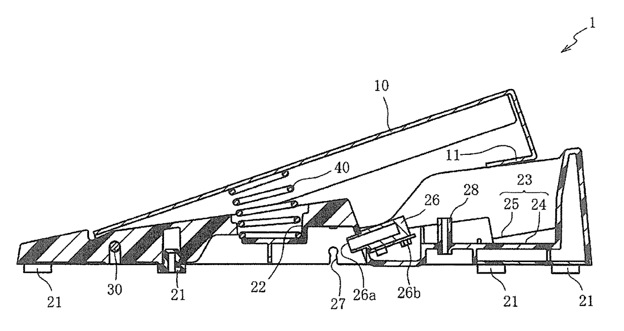
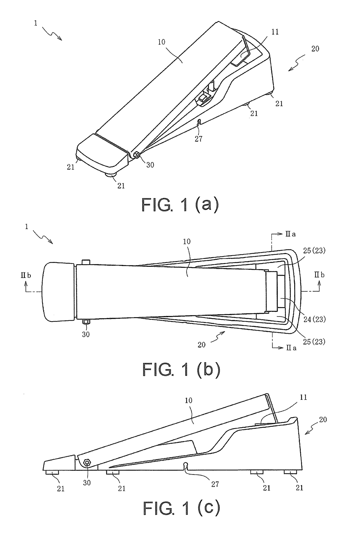
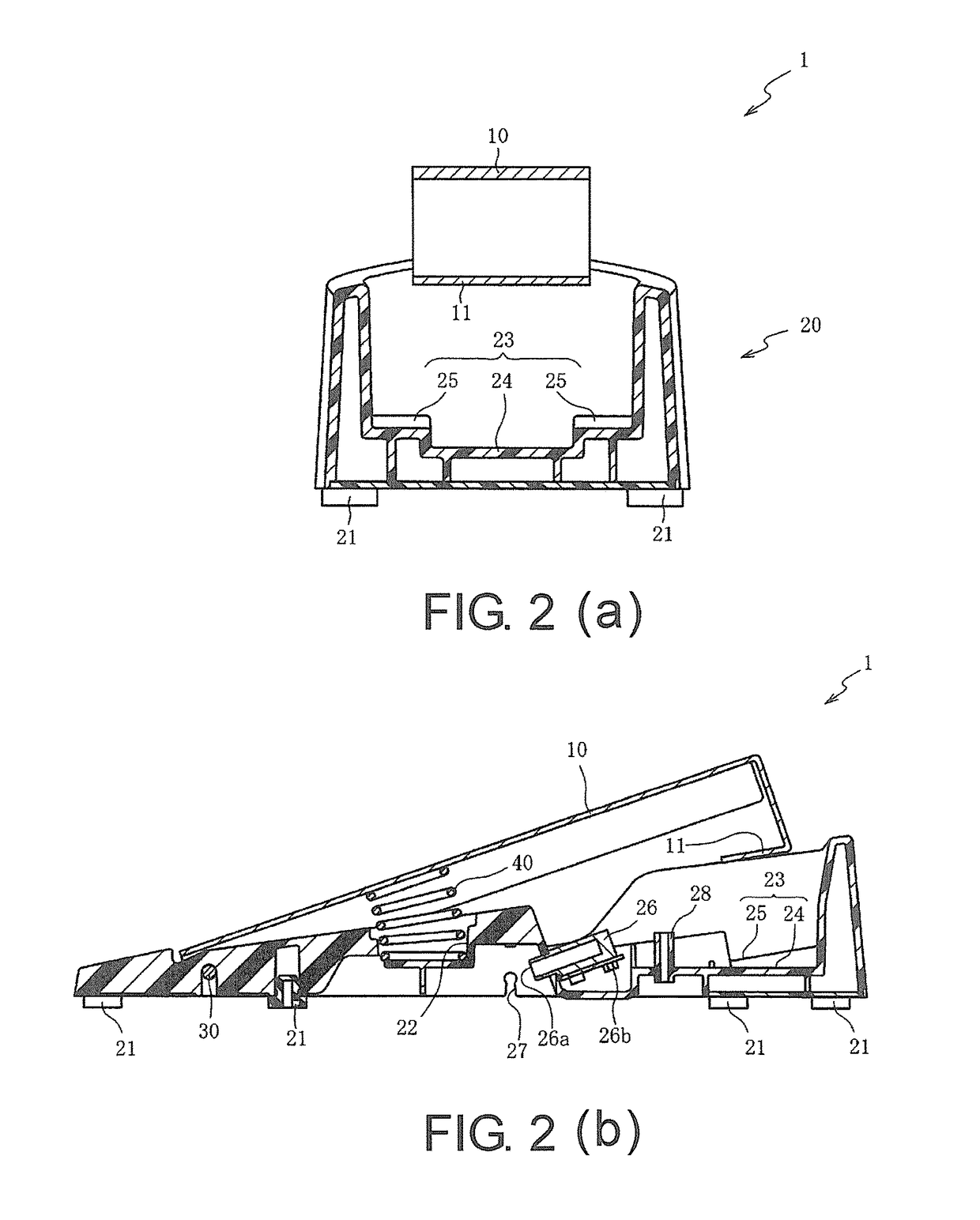
[0049]Below exemplary embodiments of the invention are described with reference to the affixed figures. First, the general structure of a pedal device 1 of the first embodiment is described with reference to FIG. 1(a), FIG. 1(b), and FIG. 1(c). FIG. 1(a) is a perspective view of the pedal device 1 according to the first embodiment of the invention. FIG. 1(b) is a top view of the pedal device 1. FIG. 1(c) is a side view of the pedal device 1.

[0050]As shown in FIG. 1(a) to FIG. 1(c), the pedal device 1 constitutes a part of a pedal device 2 for electronic hi-hat (see FIG. 3(b)) or a pedal device 3 for electronic bass drum (see FIG. 4(b)), which will be described later. The pedal device 1 mainly includes a pedal 10 and a base 20. The pedal 10 is provided to be operated by the player. The base 20 serves as a foundation. A rotation shaft 30 axially passes through one longitudinal end side of the pedal 10 (left side of FIG. 1(c)) and one longitudinal end side of the base 20 (left side of ...


PUM


Abstract

A pedal device for an electronic percussion instrument is provided, wherein first and second detection means for detecting a rotation of a pedal by different methods are alternatively disposed in a base. The pedal has a pressing part on a lower surface side. The base includes a first portion located under the pressing part for supporting the first detection means, and a second portion located around the first portion for supporting the second detection means. The first portion supports the first detection means such that a first pressed part of the first detection means is disposed on a displacement trajectory of the pressing part that displaces with the rotation of the pedal, and the second portion disposes the second detection means such that a second pressed part of the second detection means is disposed on the displacement trajectory of the pressing part.

Description

CROSS-REFERENCE TO RELATED APPLICATIONS[0001]This application claims the priority benefit of Japan application serial no. 2014-141830, filed on Jul. 9, 2014. The entirety of the above-mentioned patent application is hereby incorporated by reference herein and made a part of this specification.BACKGROUND OF THE INVENTION[0002]Field of the Invention[0003]The invention relates to a pedal device for an electronic percussion instrument. In particular, the invention relates to a pedal device for an electronic percussion instrument, which is capable of accurately detecting rotation of a pedal and achieves part commonality.[0004]Description of Related Art[0005]Among pedal devices that have a pedal configured to rotate when stepped by the player, some pedal devices simulate hi-hat or bass drum to be used in an electronic percussion instrument with a detection means for detecting rotation of the pedal.[0006]The pedal device for the electronic percussion instrument that simulates hi-hat and th...

Claims


Application Information

Patent Timeline
Patent Type & Authority Patents(United States)
IPC IPC(8): G10D13/00G10H3/00G10H1/34
CPCG10D13/006G10D13/00G10H1/348G10H2250/435G10D13/02G10D13/11
Inventor MORI, YOSHIAKI
Owner ROLAND CORP
Why Eureka
Try Eureka