Defining and implementing sensor triggered response rules

a sensor and response technology, applied in the field of security, monitoring and automation, can solve the problems of limiting the flexibility and versatility of automation and monitoring systems

Active Publication Date: 2017-08-08
ICONTROL NETWORKS
View PDF833 Cites 164 Cited by
  • Summary
  • Abstract
  • Description
  • Claims
  • Application Information

AI Technical Summary

Problems solved by technology

This limits the flexibility and versatility of the automation and monitoring systems and ties such systems to proprietary architectures.

Method used


Image

  • Defining and implementing sensor triggered response rules
  • Defining and implementing sensor triggered response rules
  • Defining and implementing sensor triggered response rules

Examples


Embodiment Construction

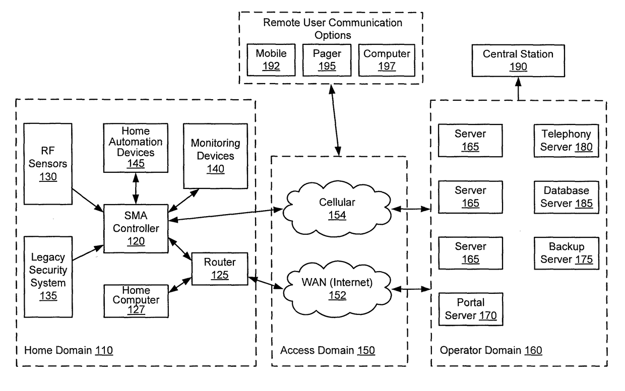
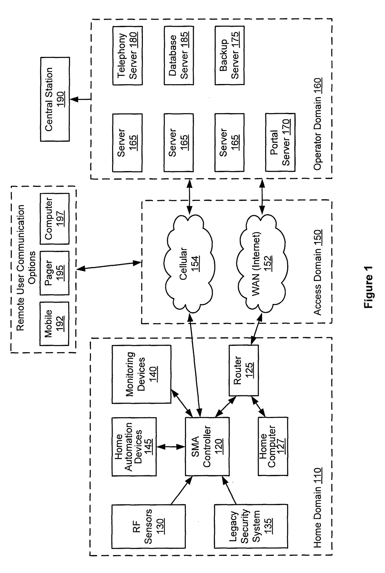
[0029]Embodiments of the present invention provide a single platform that provides controller functionality for each of security, monitoring and automation, as well as providing a capacity to function as a bidirectional Internet gateway. Embodiments of the present invention provide such functionality by virtue of a configurable architecture that enables a user to adapt the system for the user's specific needs. Embodiments of the present invention further provide for user configurable rules that associate sensor events with corresponding actions by other sensors, monitoring devices, and automation devices.

Architectural Overview

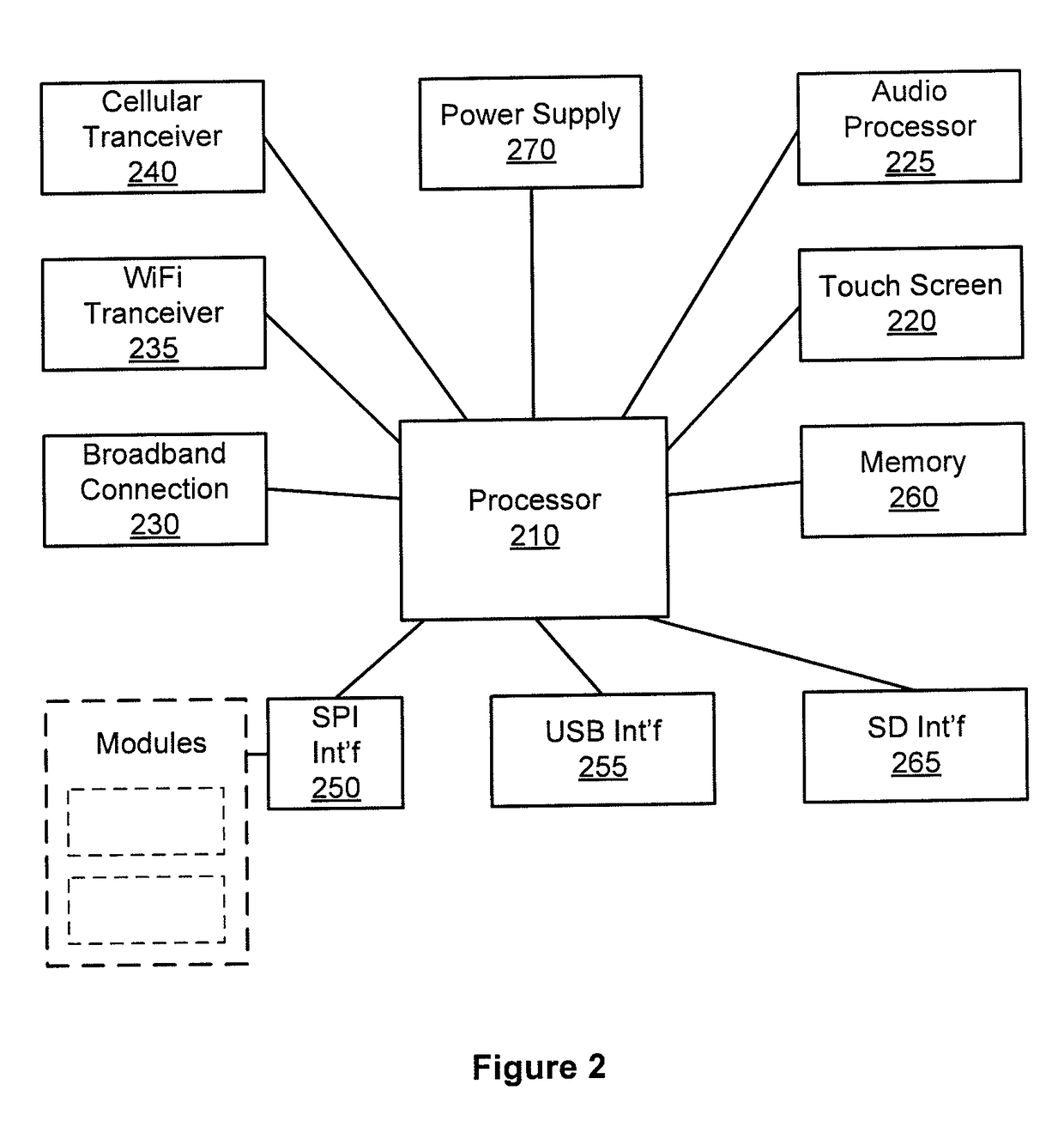
[0030]Embodiments of the configurable security, monitoring and automation (SMA) controller of the present invention provide not only for communicating with and interpreting signals from sensors and devices within a dwelling, but also for accessing and monitoring those sensors and devices from locations remote to the dwelling. Embodiments of the SMA controller p...


PUM


Abstract

A single controller platform for controlling and monitoring security, home automation, and monitoring devices is provided. This controller platform further provides for a rules-based response to receiving sensor events, including causing actions to be performed by the controller platform or to cause actions to be performed by sensor devices.

Description

FIELD OF THE INVENTION[0001]Embodiments of the present invention relate generally to the field of premises security, monitoring and automation, and specifically to a user-configurable rules engine for implementing sensor triggered response actions.BACKGROUND OF THE INVENTION[0002]Residential electronics and control standards provide an opportunity for a variety of options for securing, monitoring, and automating residences. Wireless protocols for transmission of security information permit placement of a multitude of security sensors throughout a residence without a need for running wires back to a central control panel. Inexpensive wireless cameras also allow for placement of cameras throughout a residence to enable easy monitoring of the residence. A variety of home automation control protocols have also been developed to allow for centralized remote control of lights, appliances, and environmental apparatuses (e.g., thermostats). Traditionally, each of these security, monitoring ...

Claims


Application Information

Patent Timeline
Patent Type & Authority Patents(United States)
IPC IPC(8): G06F17/00H04L12/28
CPCH04L12/2827G08B29/02
Inventor COHN, ALAN WADEDIAL, IV, JOHN DEGRAFFENREIDFAULKNER, GARY ROBERTKITCHEN, JAMES EDWARDPROFT, DAVID LEONQUAIN, COREY WAYNE
Owner ICONTROL NETWORKS
Why Eureka
Try Eureka