Motor vehicle armrest

a technology for motor vehicles and armrests, which is applied in the direction of vehicle components, pedestrian/occupant safety arrangements, vehicle arrangements, etc., can solve the problems of the above-mentioned armrests that need to be improved, and achieve the effects of enhancing riding comfort, and improving the stability of the occupant's attitud

Active Publication Date: 2017-08-22
HONDA MOTOR CO LTD
View PDF8 Cites 6 Cited by
  • Summary
  • Abstract
  • Description
  • Claims
  • Application Information

AI Technical Summary

Benefits of technology

[0008]The present application describes a motor vehicle armrest that can improve attitude stability of an occupant in the vehicle-width direction.
[0009]A first aspect of the present application provides a motor vehicle armrest (for example, an armrest 5 in an embodiment) having an armrest body (for example, armrest bodies 11A, 11B in the embodiment) that is disposed on at least one side in a vehicle-width direction of a seat cushion (for example, a seat cushion 2 in the embodiment) so as to support an arm of an occupant, in which the armrest body has an inflation portion (for example, an inflation portion 22 in the embodiment) that is inflated toward the occupant in the vehicle-width direction so as to support the occupant in the vehicle-width direction. With this arrangement, the occupant can be prevented from getting out of a proper position in the vehicle-width direction during, for example, turning or other normal operation of the vehicle whereby the attitude stability of the occupant can be improved, which results in enhanced riding comfort.
[0010]A second aspect of the present application provides the motor vehicle armrest in which the armrest body may be disposed on each side in the vehicle-width direction of the seat cushion. With this arrangement, the occupant can be supported from both sides. This improves the attitude stability as well as the riding comfort of the occupant.
[0011]A third aspect of the present application provides the motor vehicle armrest in which the armrest body disposed on the side of a door opening (for example, a door opening 6 in the embodiment) may have a side impact load reducing portion (for example, a padding material 21 in the embodiment) that protects the occupant against an impact coming from a side of the vehicle and in which the armrest body disposed on the opposite side of the seat cushion from the door opening may overlap the occupant in side view as seen from the vehicle-width direction and may be movable between a use position at which the armrest body supports the arm of the occupant and a stowed position at which the armrest body does not overlap the occupant. With this arrangement, the occupant can move the armrest body in accordance with the occupant's preference. When put in the stowed position, the armrest body does not overlap the occupant in side view as seen from the vehicle-width direction, creating a space on the opposite side of the seat cushion from the door opening. This can satisfy both of safety against a vehicle crash and interior comfort of the passenger compartment.
[0012]A fourth aspect of the present application provides the motor vehicle armrest in which the armrest body disposed on the side of the door opening may be movable between the use position at which the armrest body protrudes above the seat cushion so as to support the arm of the occupant and the stowed position that is located below the use position. With this arrangement, the occupant can move the armrest body in accordance with the occupant's preference. When put into the stowed position, the armrest body is disposed below the use position, enabling the occupant to enter and exit the vehicle through the armrest body. In other words, the armrest body provides support for the occupant entering and exiting the vehicle, thereby improving the convenience of the occupant.

Problems solved by technology

However, the armrests described above need to be improved because of a problem with the attitude stability in the vehicle-width direction of the occupant during, for example, turning or other normal operations.

Method used


Image

  • Motor vehicle armrest
  • Motor vehicle armrest
  • Motor vehicle armrest

Examples


first embodiment

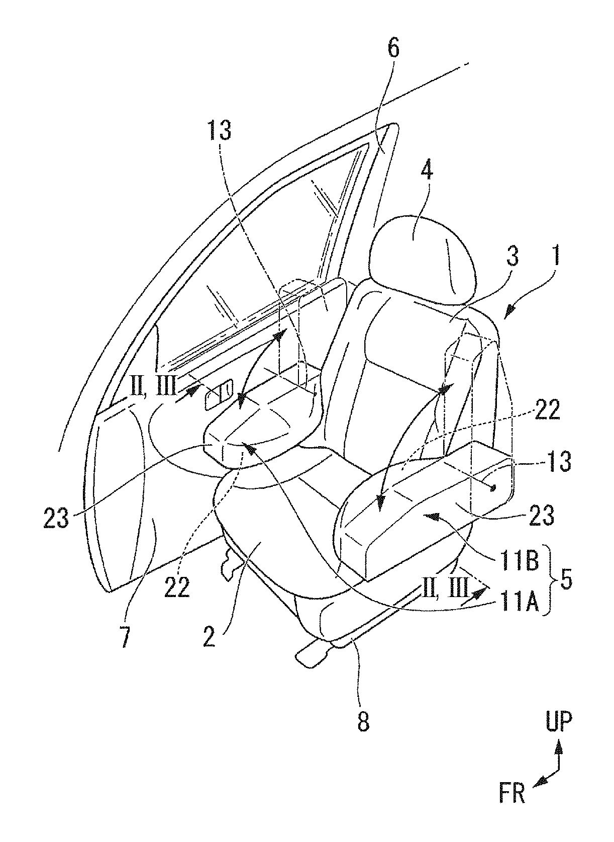
[0020]FIG. 1 is a perspective view of a driver's seat 1 of a vehicle. The seat 1 shown in FIG. 1 is provided with a seat cushion 2, a seat back 3 tiltably coupled to a rear end of the seat cushion 2, a head rest 4 supported on the top of the seat back 3, and an armrest 5 disposed on a side of the seat cushion 2. A component indicated by a numeral “6” in FIG. 1 is a door opening through which an occupant of the vehicle enters and exits and which is opened and closed by a front side door 7.

[0021]The seat cushion 2 supports a region ranging from the buttocks to the thigh of the occupant from below and is supported on a vehicle floor via a seat rail 8 so as to be longitudinally slidable. The seat back 3 supports a region from the lumber to the back of the occupant from the rear and is longitudinally tiltable whereby its angle is adjusted relative to the seat cushion 2. The head rest 4 supports the head of the occupant and is mounted on the seat back 3 so as to be liftable.

[0022]The armr...

second embodiment

[0033]Next, a second embodiment of the present application will be described below. FIG. 5 is a front view of a seat 1 as seen from the front, explaining an armrest 5 according to a second embodiment. As shown in FIG. 5, in this embodiment, an armrest body 11A on the side of the door opening 6 is mounted on the seat cushion 2 so as to be rotatable around a rotating shaft 31 extending in the longitudinal direction. Specifically, the armrest body 11A is rotatable between a use position at which the occupant's arm can be placed on the armrest and a stowed position at which the inflation portion 22 faces upward after the armrest body 11A is rotated from the use position to the outer side in the seat-width direction. The armrest body 11A, when put in the stowed position, makes a bridge between the seat cushion 2 and a step garnish 32 defining the door opening 6 in such a manner that the inflation portion 22 is arranged at the same height as that of the seat cushion 2.

[0034]In addition to...


PUM


Abstract

A motor vehicle armrest includes an armrest body that is disposed on at least one side in a vehicle-width direction of a seat cushion so as to support of an arm of an occupant. The armrest body has an inflation portion that is inflated toward the occupant in the vehicle-width direction so as to support the occupant in the vehicle-width direction.

Description

CROSS REFERENCES TO RELATED APPLICATIONS[0001]The present application claims priority under 35 U.S.C. §119 to Japanese Patent Application No. 2015-087456, filed Apr. 22, 2015, entitled “Motor Vehicle Armrest.” The contents of this application are incorporated herein by reference in their entirety.BACKGROUND[0002]1. Field[0003]The present disclosure relates to a motor vehicle armrest.[0004]2. Description of the Related Art[0005]To date, motor vehicles have been equipped with armrests that protect arms of occupants seated in their seats. From, for example, Japanese Unexamined Utility Model (Registration) Application Publication No. 1-70645, there is known an armrest that has a bag for containing a fluid and that changes the thickness of the bag by causing a fluid to go into the bag and thereby adjusts the height of the armrest.[0006]In addition, an armrest disclosed in Japanese Unexamined Patent Application Publication No. 2003-220913 has a structure in which a cushioning material is ...

Claims


Application Information

Patent Timeline
Patent Type & Authority Patents(United States)
IPC IPC(8): B60N2/46B60N2/42B60R21/207B60R21/04B60N2/75
CPCB60N2/4626B60N2/4235B60N2/4606B60N2/4633B60R21/04B60R21/207B60R2021/0407B60N2/763B60N2/753B60N2/767
Inventor HONDA, TAKASHIFUJIMAKI, TAKESHI
Owner HONDA MOTOR CO LTD
Why Eureka
Try Eureka