Storage system and data management method

a storage system and data management technology, applied in the direction of memory adressing/allocation/relocation, instruments, input/output to record carriers, etc., can solve the problems of insufficient utilization of flash devices, inability to apply to the migration between storage apparatuses that handle different formats, and the possibility of frequent migration between storage apparatuses of different formats

Active Publication Date: 2017-08-22
HITACHI LTD
View PDF13 Cites 0 Cited by
  • Summary
  • Abstract
  • Description
  • Claims
  • Application Information

AI Technical Summary

Benefits of technology

[0014]With this invention, load of processing in a storage apparatus in the case where it is necessary to convert the format of data can be reduced, and the storage apparatus can be utilized at an early point.

Problems solved by technology

Since the performance of the flash drive is high in such a storage apparatus, there is a problem that a microprocessor (MP) included in a controller of the storage apparatus becomes a bottleneck and the resource of a flash device cannot be utilized sufficiently.
However, this technique assumes that the physical format (block size) or the format of a data guarantee code or the like is the same for data handled by a storage apparatus before migration and a storage apparatus after migration, and cannot be applied to migration between storage apparatuses that handle different formats.
Thus, there may be a possibility of migrations between storage apparatuses of different formats occurring frequently.

Method used


Image

  • Storage system and data management method
  • Storage system and data management method
  • Storage system and data management method

Examples


example 1

[0036]First, an overview of a storage system according to Example 1 will be described.

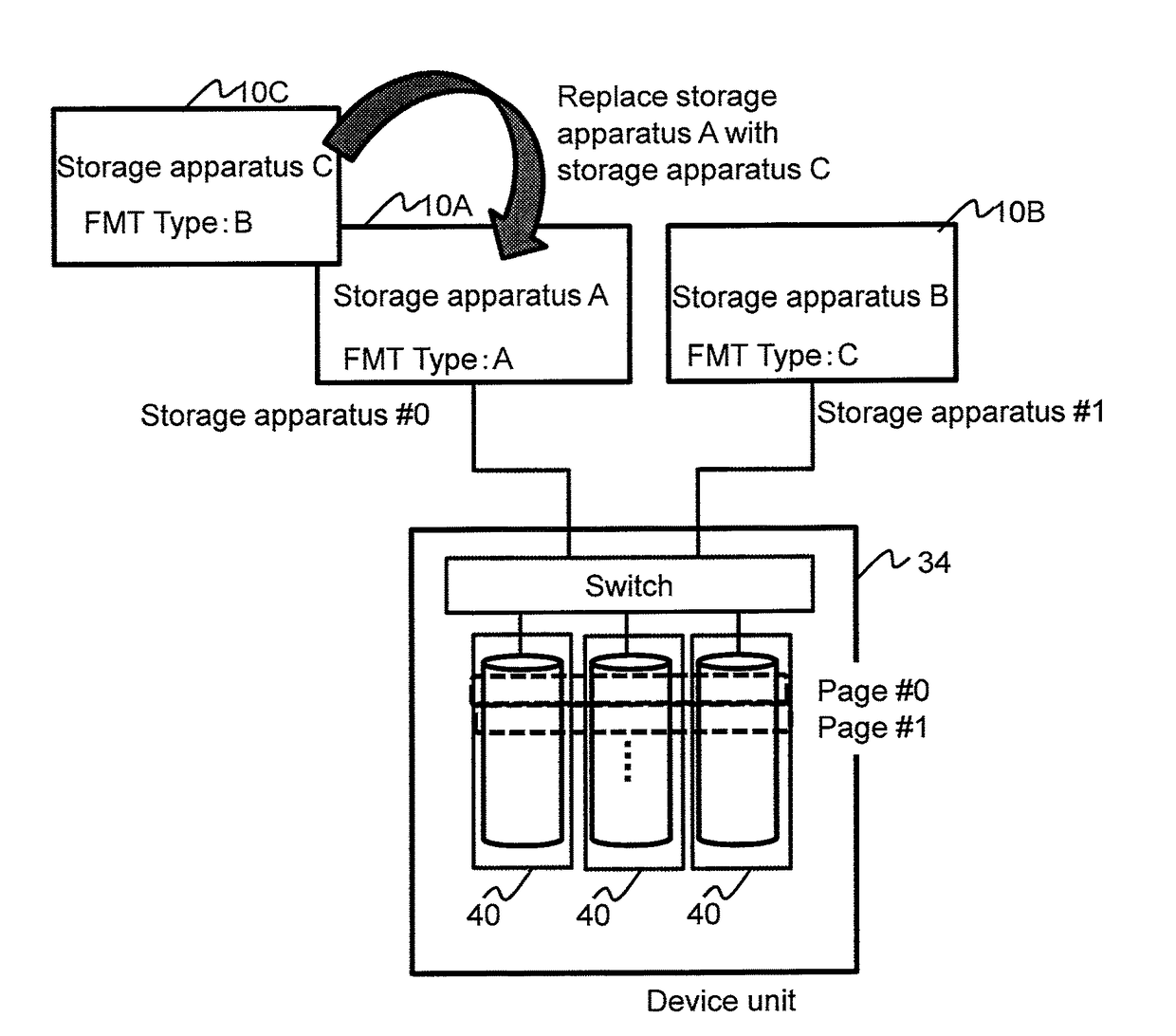
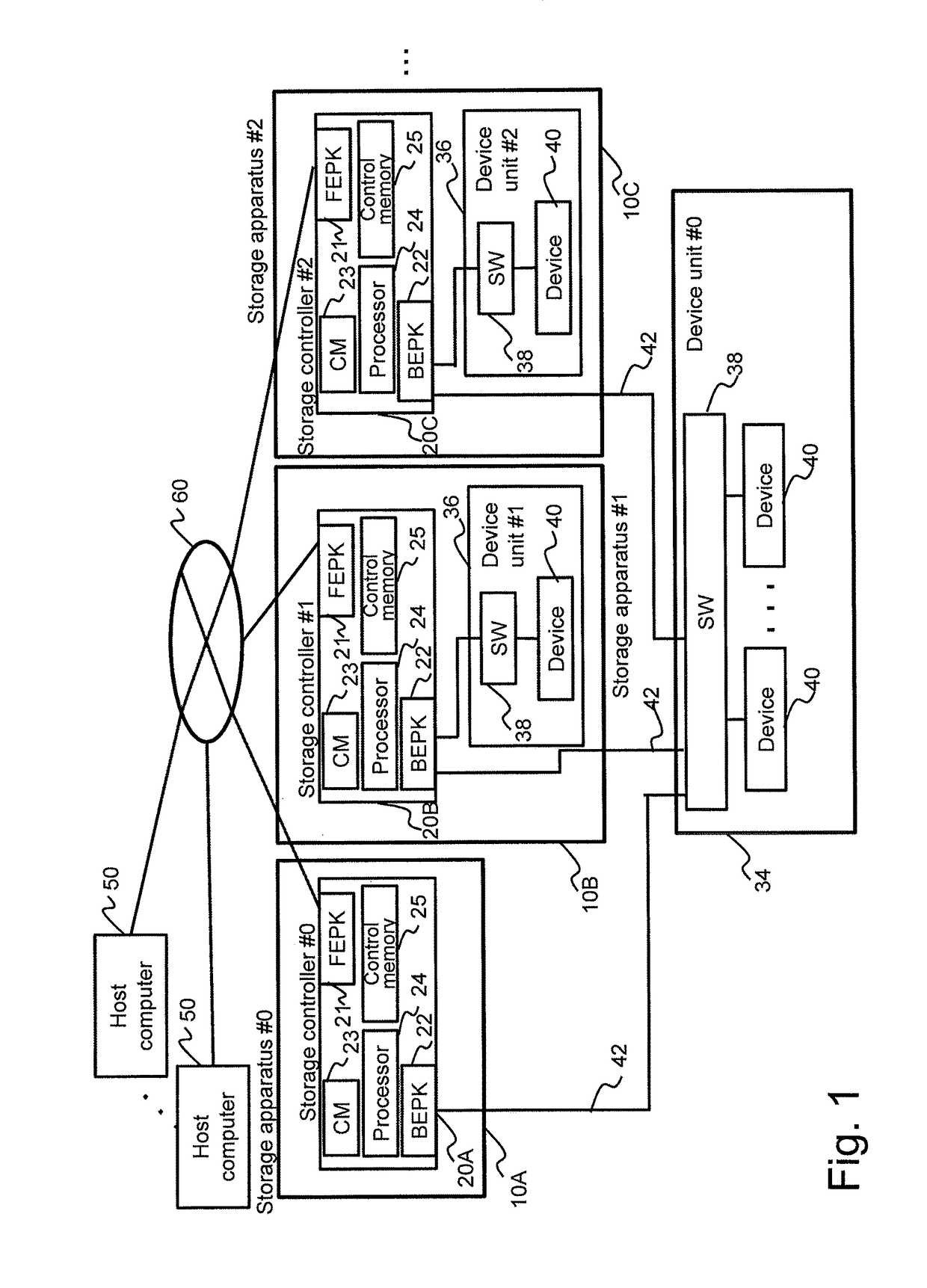
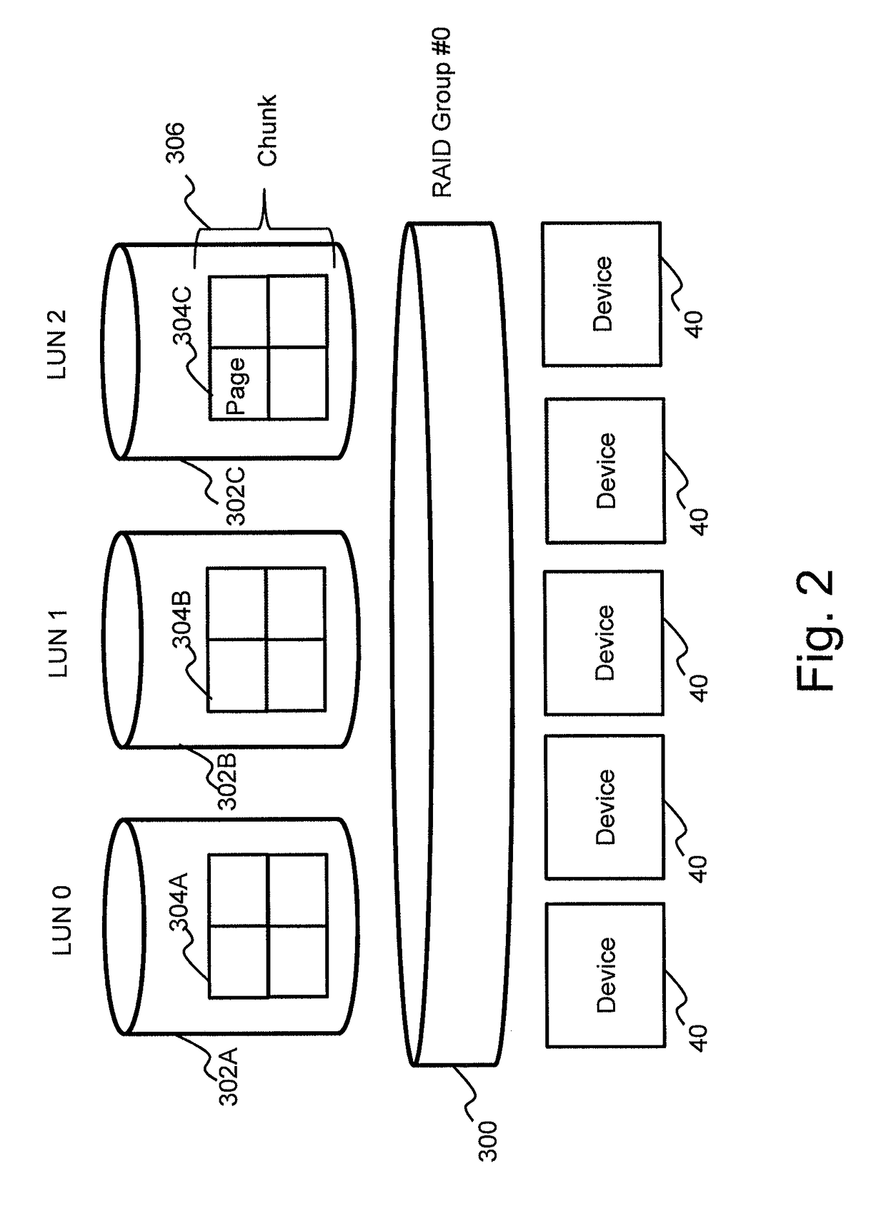
[0037]In the storage system according to Example 1, a plurality of storage apparatuses 10 share one device unit (shared device unit) 34, as shown in FIG. 1. Specifically, for example, a storage area within the one device unit 34 is divided, and a divided storage area (device allocation area) is allocated to each storage apparatus 10, so that the respective storage apparatuses 10 can share the device unit 34. For example, the device allocation area may be provided to a host computer as a logical unit (LU) that is a logical storage device (may be an online LU), or may be a storage area (e.g., offline LU) that is used by the storage apparatus 10 without being provided to a host computer 10.

[0038]In the storage system, a device (storage device) 40 included in the shared device unit 34 manages, for each predetermined area unit (e.g., for each page unit), the format type (information for identifying a fi...

example 2

[0133]Next, the details of a storage system according to Example 2 will be described below.

[0134]A storage system according to Example 2 is a storage system shown in FIG. 1, the storage system being such that a device (first storage device) having a function (format conversion function) of executing the reclamation processing, the device Read processing, and the device Write processing according to Example 1 and a device (second storage device: e.g., a general HDD) not having the format conversion function coexist as the device 40.

[0135]The storage apparatus 10 according to Example 2 is configured to execute storage Read processing and storage Write processing below that are new.

[0136]FIG. 17 is a flowchart of the storage Read processing according to Example 2.

[0137]The storage Read processing is processing executed in the case where the storage apparatus 10 has received a Read command from the host computer 50.

[0138]Upon receiving the Read command from the host computer 50 (step 11...


PUM


Abstract

A storage system comprises a storage apparatus and a storage device that is a basis for a storage area provided to the storage apparatus. The storage device determines whether or not a first format that is a format of data stored in the storage device and a second format that is a format of data utilized by the storage apparatus managing the data match with each other, and performs format conversion of either converting data in the first format to data in the second format or converting data in the second format to data in the first format in a case where the first format and the second format do not match with each other.

Description

TECHNICAL FIELD[0001]The present invention relates to a data management technique in a storage system.BACKGROUND ART[0002]In recent years, flash memories have become lower in price, and a high-speed flash drive (e.g., solid state drives (SSD)) including flash memory is installed in storage systems as well. Since the performance of the flash drive is high in such a storage apparatus, there is a problem that a microprocessor (MP) included in a controller of the storage apparatus becomes a bottleneck and the resource of a flash device cannot be utilized sufficiently.[0003]In this regard, a technique in which a flash drive is shared and used by a plurality of storage apparatuses has been devised. In this technique, one of the purposes is to render data movement unnecessary even in the case of migration from an existing storage apparatus to a new-generation storage apparatus.[0004]However, this technique assumes that the physical format (block size) or the format of a data guarantee code...

Claims


Application Information

Patent Timeline
Patent Type & Authority Patents(United States)
IPC IPC(8): G06F12/02G06F3/06
CPCG06F3/0629G06F3/061G06F3/064G06F3/067G06F3/0608G06F3/0661G06F3/0689G06F3/0607
Inventor MATSUI, YUKOHOMMA, SHIGEO
Owner HITACHI LTD
Why Eureka
Try Eureka