
Method of production of secondary steel based on scrap

a scrap and secondary steel technology, applied in the direction of manufacturing converters, furniture, lighting and heating apparatus, etc., can solve the problems of increased additional expenses, undefined and non-stationary oxidation conditions of accompanying products, and expensive flue gas treatment, so as to achieve the effect of preventing or at least minimizing the amount of was

Inactive Publication Date: 2011-03-22
SMS DEMAG AG
View PDF1 Cites 0 Cited by
  • Summary
  • Abstract
  • Description
  • Claims
  • Application Information

AI Technical Summary

Benefits of technology

The scrap after leaving the preheater is “clean”, i.e., all of clinging hydrocarbons were converted into a gas phase. Thereby, the loading of the process gas with dust at the outlet of the melting stage, in comparison with a conventional process, is substantially prevented.
In comparison with a conventional process, secondary or spatial dedusting can be dispensed with as all of the components can be made gastight. This permits a noticeable reduction in the to-be-treated flue gas amount and, thereby, of the size of separate installation components. Due to the inventive energy decoupling of process stages melting-preheating-post-combustion, the process can be conducted with high flexibility and, simultaneously, with high energy efficiency.
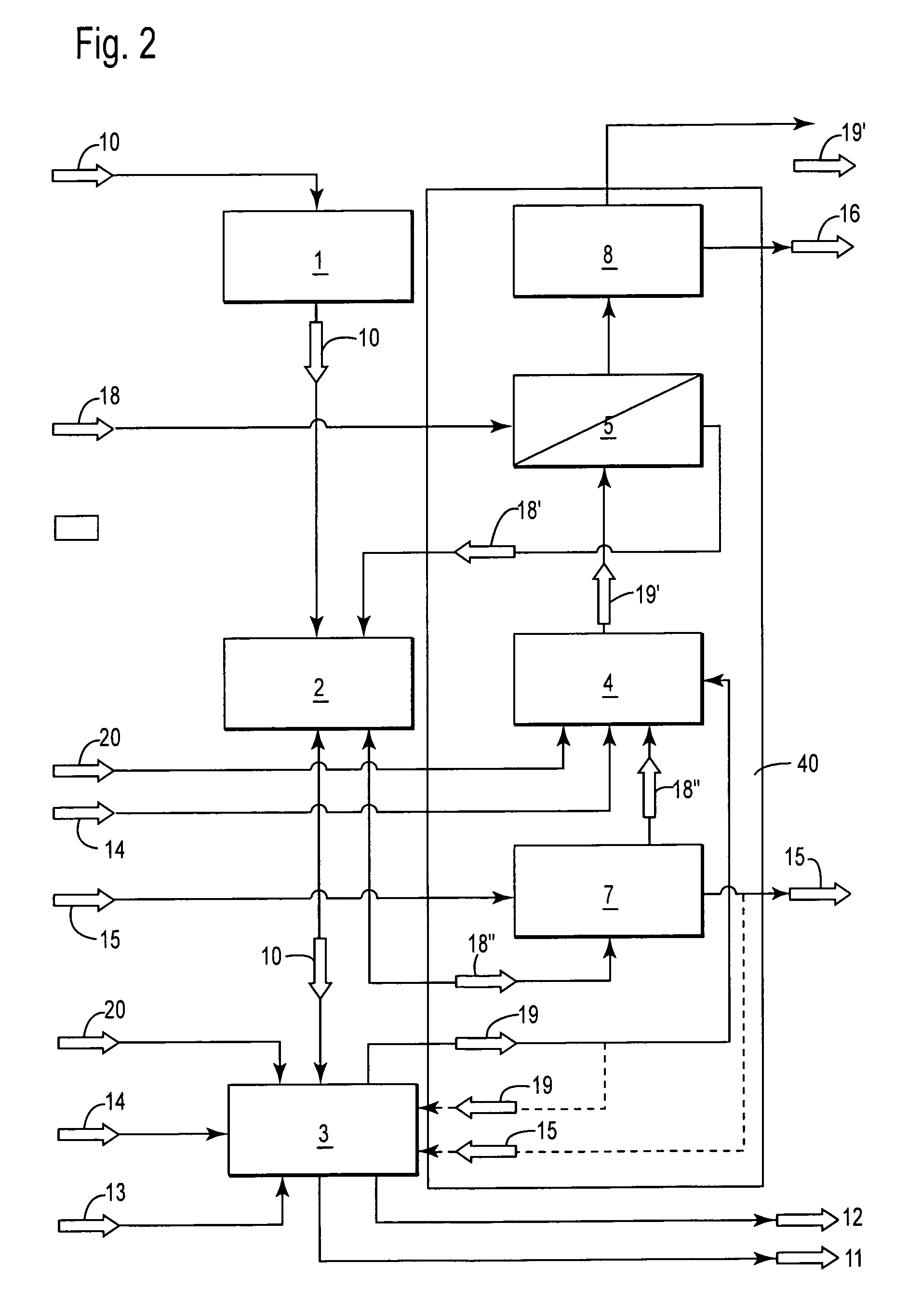
According to the invention, additional bypass conduits can be provided in the hot air loop in order to improve the temperature control of the entire process:Admixing of cold air to the warm air, which is loaded with harmful materials, at the outlet of the scrap preheater for controlling the entry temperature in the adsorbtion device.Returned of the clean warm air directly in the fresh air stream in front of the heat exchanger for controlling the temperature in the reheating device.Use of a portion of the hot air as oxidation means for the smelting unit. The feeding can be effected directly in the melting zone.Use of a portion of the hot air as oxidation means for post-combustion. Thereby, the flue gas temperature can be increased or retained constant at a low residual calorific value or at a small amount of the process gas (small melting capacity). This expansion is advantageous for carrying out the process, starting from a cold condition for rapidly reaching the production temperature.
Thereby, a most possible decoupling of the combustion stage from the preheating stage is effected, whereby high scrap temperatures at the outlet of the preheater can be realized. This results in that technical and economical limits of the process can be set as a result of ever diminishing oxidation with increase of the gas temperature.

Problems solved by technology

This leads to undefined and non-stationary oxidation conditions of accompanying products which cling to the scrap.
In order to meet the legal requirements, an expensive flue gas treatment is necessary to eliminate and separate the non-combusted hydrocarbons and dioxins / furans.
This type of a process insures maintaining of emission threshold for PCDD / F of 0.01 ng TE / Nm3 but, however, is associated with increased additional expenses (for the primary energy for the burner, cooling water for quenching, waste water treatment system for quenching, silo, metering and delivery technique for the coke dust, etc.).
In addition, additional devices become responsible for additional disturbances in the installation.
This results in a poor use of the used energy carrier.
Therefore, further measures are necessary in order to improve the energy use which results in increased costs.
This measure improves the energy use, however, for different reasons, probably, no complete conversion of non-combusted materials in the shaft is possible.

Method used


Image

  • Method of production of secondary steel based on scrap
  • Method of production of secondary steel based on scrap
  • Method of production of secondary steel based on scrap

Examples


Embodiment Construction

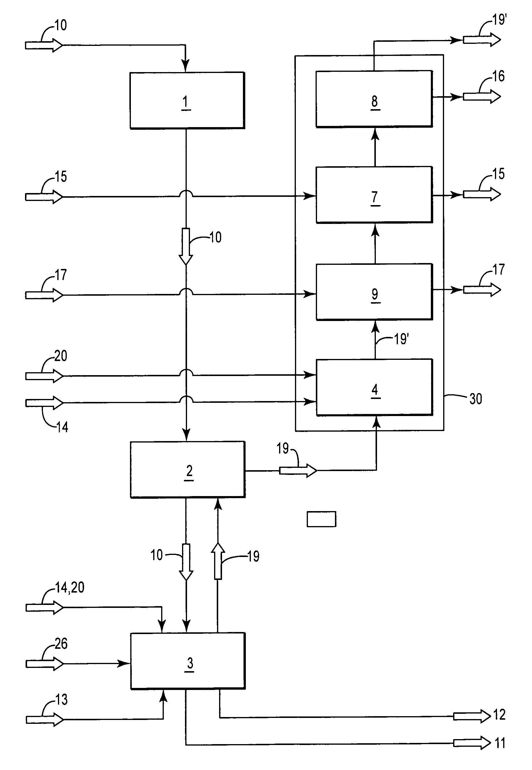
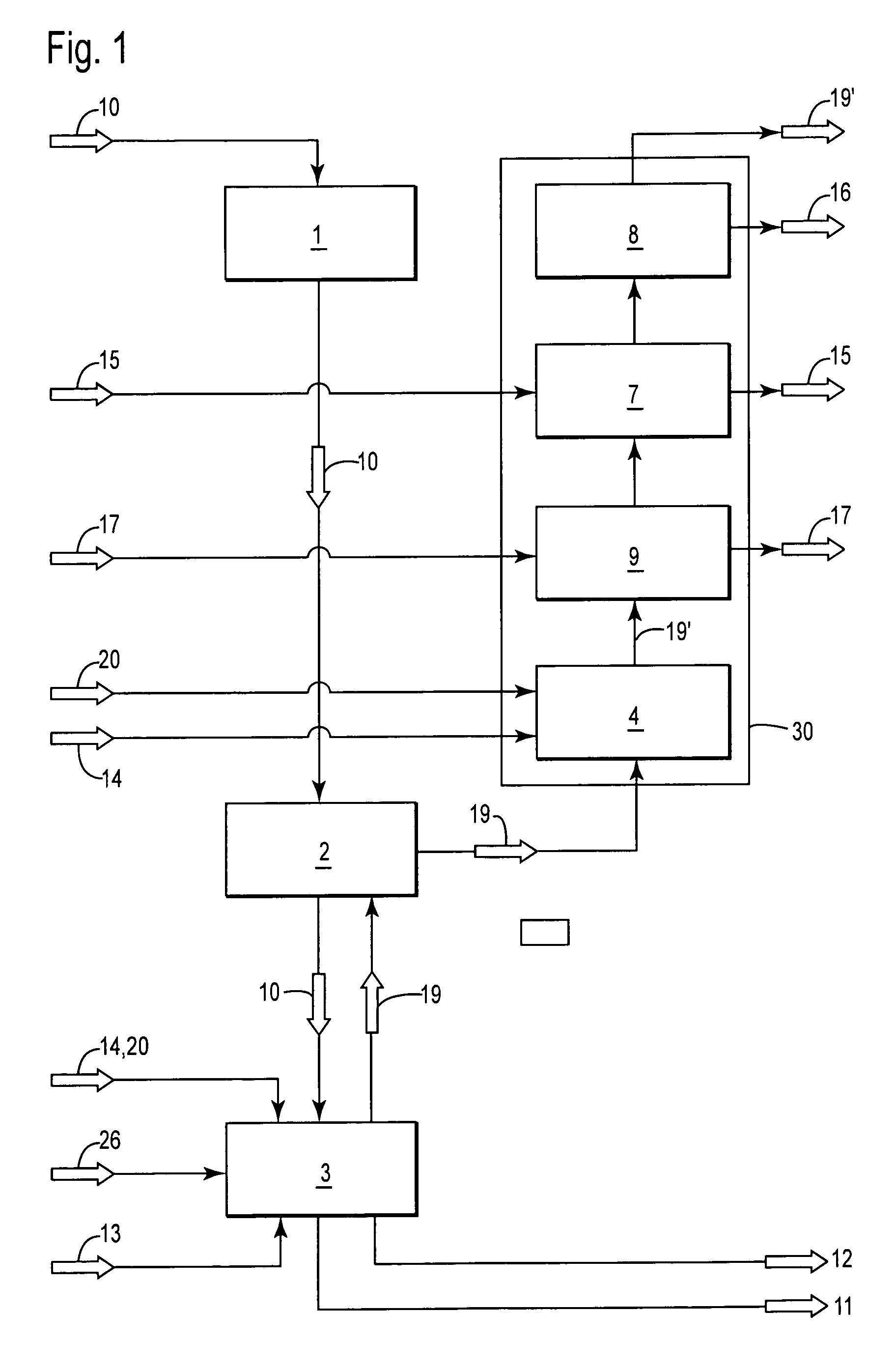
FIG. 1 shows a simplified basic flow chart of a typical flue gas cleaning of a melting process with scrap preheating. Scrap 10 is fed to a scrap preheater 2 through a charging device 1 and is heated there with process gas 19 of a smelting unit 3. The heated scrap 10 is then fed in the smelting unit 3 where it is melted with addition of oxygen 20 and additives 13, by a fossil and / or electrical energy, and leaves the smelting unit 3 as melt 11 and flux 12.

After leaving the scrap preheater 2, the process gas 19 is fed to a flue gas treatment system 30 where it is reheated, with addition of oxygen 20, by fossil energy 14. The flue gas 19′, which was produced in the reheating unit 4, is then cooled in a cooling device 9 with water 17, is freed from harmful materials in an adsorbtion device 7 by addition of an adsorbent 15 and, finally, is separated from dust 16 in a dedusting apparatus 8.

FIG. 2 shows a simplified scheme of an inventive flue gas treatment system 40 with an open preheating...


PUM

PropertyMeasurementUnit
temperatureaaaaaaaaaa
separationaaaaaaaaaa

Abstract

With the production of the secondary steel based on scrap, wherein the scrap (10) is fed in a scrap preheater (2) through a charging device (1), is preheated there and, finally, is brought into a smelting unit (3) and is melted there with primary energy only, the process gases (19), which leave the smelting unit (3), are not used for directly preheating the scrap (10) but are rather used indirectly by heating a gaseous preheatable medium, e.g., air (18) or inert gas, so that energetic, fluidic, and spatial decoupling of preheating and melting and of post-combustion and preheating is achieved.

Description

BACKGROUND OF THE INVENTION1. Field of the InventionThe invention relates to a method of production of secondary steel based on scrap, wherein the scrap is fed in a scrap preheater through a charging device, is heated there and, finally, is brought in a smelting unit and is melted, wherein process gas which leaves the smelting unit, is used for preheating of the scrap, is freed of harmful materials and dust in a reheating device and in an adjoining dedusting installation, respectively, and is discharged from the installation as a cooled cleaned flue gas.2. Description of the Prior ArtWith such a method, the scrap is fed through a charging device in a preheater which, as a rule, is heated directly with a hot flue gas from a smelting unit, e.g., electrical arc furnace. It is mostly aspirated through the preheater, heating the scrap. The flue gas is cooled off. The preheated scrap (dependent on the process, to about 600-800° C.) is then transferred in a smelting unit and is melted with...

Claims


Application Information

Patent Timeline
Patent Type & Authority Patents(United States)
IPC IPC(8): C21C5/40C21C7/072
CPCC21C5/527C21C5/5294C21C5/565F27D13/002F27D17/00C21C5/38Y10S266/901Y02P10/20Y02P10/25C21C5/56F27D13/00C21C5/52
Inventor MEYN, MATTHIAS
Owner SMS DEMAG AG
Learn More