
Recording device, reproducing device, recording medium, recording method, and LSI

a technology of reproducing device and recording medium, applied in the direction of digitised analogue information signals, electronic editing, instruments, etc., can solve the problems of large processing load, insufficient playback apparatus, and inability to meet the demand for further simplification of recording apparatus, so as to reduce processing load, reduce processing load, and not very high data size

Active Publication Date: 2012-07-03
PANASONIC INTELLECTUAL PROPERTY CORP OF AMERICA
View PDF16 Cites 0 Cited by
  • Summary
  • Abstract
  • Description
  • Claims
  • Application Information

AI Technical Summary

Benefits of technology

The present invention provides a recording apparatus that generates meta-information by generating size information showing a size of picture data that is independently decodable without being expanded to a PES. This allows for easier reading of picture data by playback apparatuses without the need for hardware sources such as a memory and reduces processing load. The generated meta-information includes an initial address of TS packets constituting a PES packet and size information pertaining to the picture. This simplifies the recording apparatus and reduces processing load, making it suitable for portable receivers for digital TV broadcasting.

Problems solved by technology

Meanwhile, when performing random access on a recording medium, address information that shows the position of the head of picture data as a “point” is not enough for a playback apparatus to read independently-decodable picture data.
However, since expansion to a PES requires hardware sources such as a memory, it is impossible to meet the demand for further simplification of the recording apparatus.
Moreover, since the recording apparatus is required to search a PES bit by bit for a picture header, the processing load becomes large.
Therefore, it is difficult to apply this method to a portable receiver for digital TV broadcasting.
This is the problem.

Method used


Image

  • Recording device, reproducing device, recording medium, recording method, and LSI
  • Recording device, reproducing device, recording medium, recording method, and LSI
  • Recording device, reproducing device, recording medium, recording method, and LSI

Examples


first embodiment

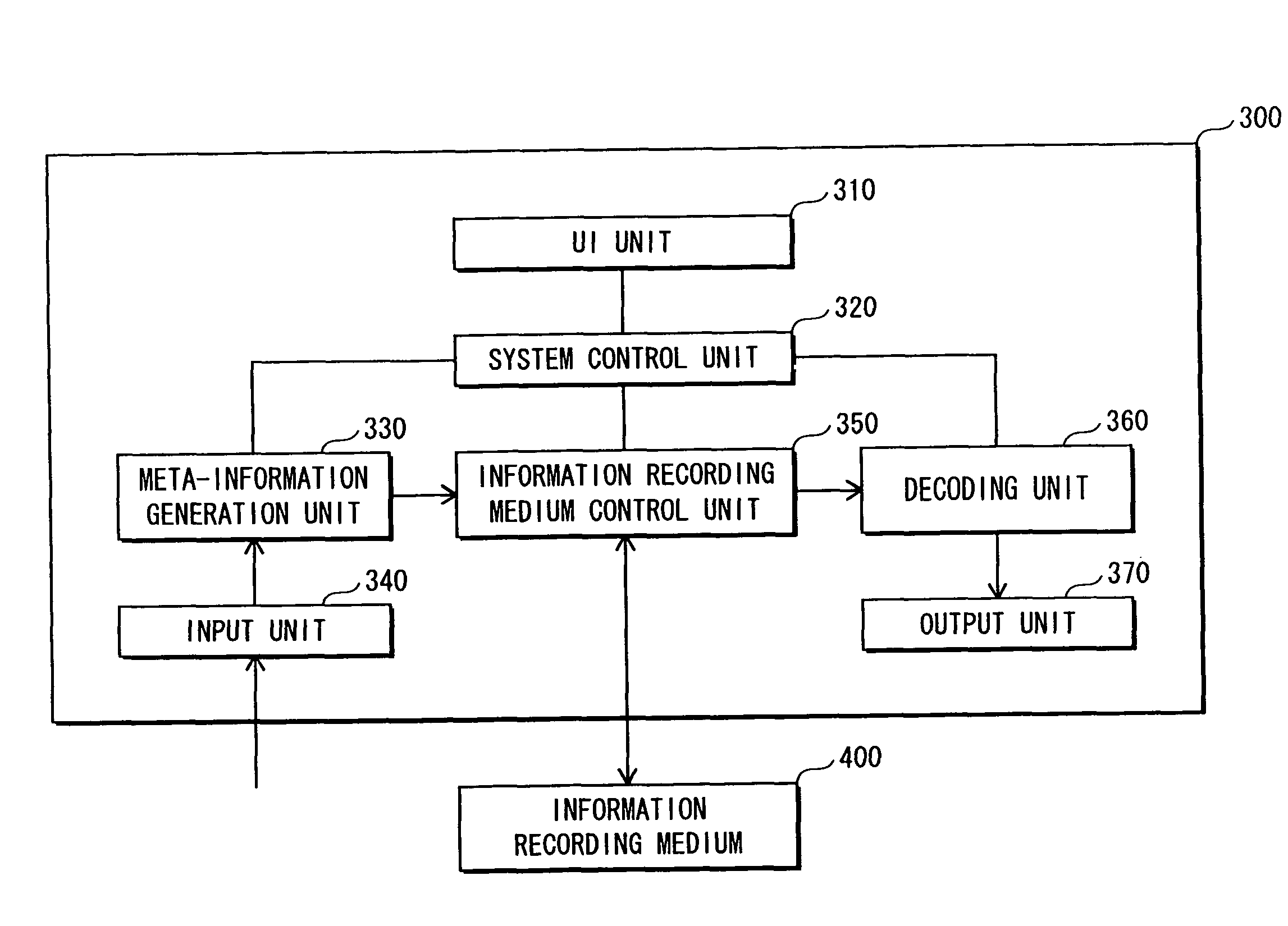
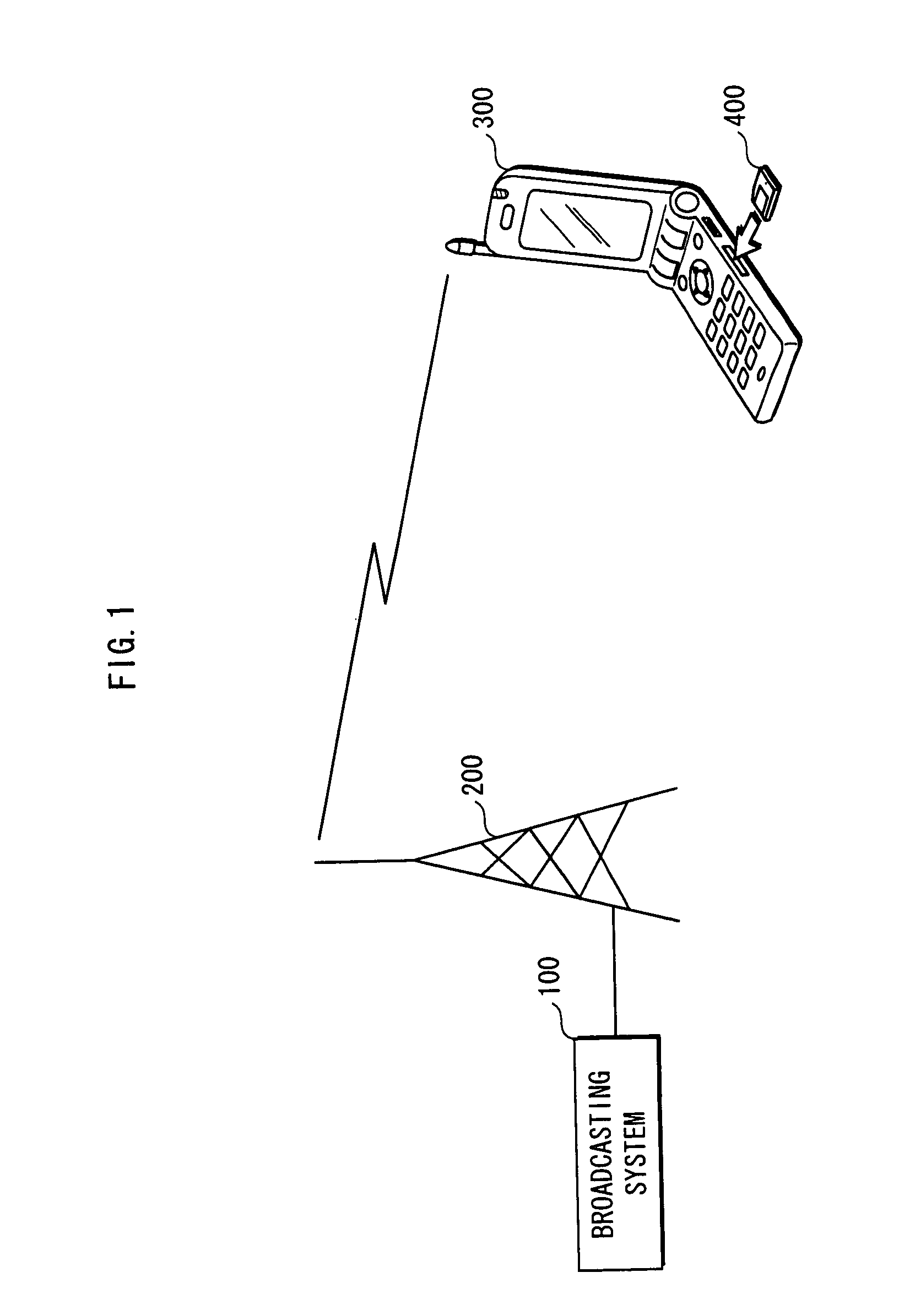
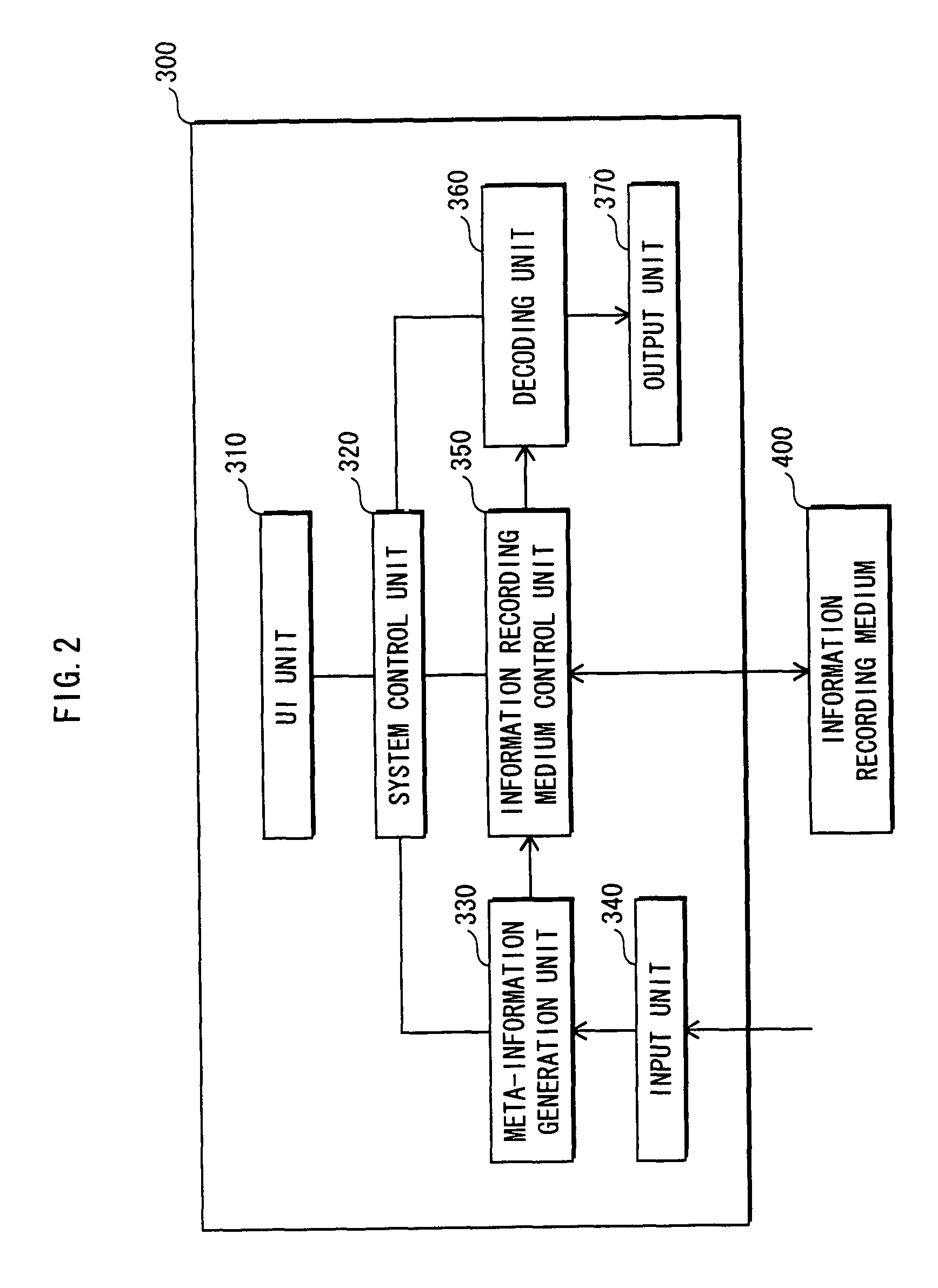
[0054]The following describe an embodiment of a recording / playback apparatus 300 pertaining to the present invention. First of all, among various acts of practicing the recording / playback apparatus pertaining to the present invention, an act of using is described. The recording / playback apparatus 300 pertaining to the present invention is used by a user in a form of a system shown in FIG. 1. The system shown in FIG. 1 includes a broadcasting system 100, a transmission antenna 200, the recording / playback apparatus 300, and an information recording medium 400.

[0055]The broadcasting system 100 is a system for generating stream data to be transmitted by digital broadcasting. The stream data to be generated is an MPEG2 transport stream of the ISO / IEC 13818-1 defined for digital broadcasting in accordance with the standard relating to the C profile of the “operational guidelines for digital terrestrial television broadcasting” (ARIB TR B-14) or a standard relating to the ARIB TR B-14. Vid...

specific examples

[0112]FIG. 12 schematically shows the idea of the present invention. In FIG. 12, the upper chart shows video frames, the middle chart shows PES packets (of only video data), and the lower chart shows TS packets. In the lower chart, “V” represents a TS packet that stores therein video data, and “A” represents a TS packet that stores therein audio data. The numbers 0 to 34 represent numbers given to TS packets respectively. As illustrated in this drawing, a PES packet is structured from a plurality of pictures, and each picture completes in a single PES packet, i.e. each picture is not divided into pieces and not separately stored in different PES packets.

[0113]Upon acquiring the TS packet V0 which is located at the head of the content, the TS packet analysis unit 331 judges whether the TS packet V0 includes a PES packet header of video data. Here, as shown in the drawing, the TS packet V0 includes a PES packet header of video data. Accordingly, the TS packet analysis unit 331 further...

second embodiment

[0121]The first embodiment attempts to reduce the processing load by approximating the size of an IDR picture using the number of TS packets included in the PES packet that has been judged as indulging the IDR picture. However, in the case of having received a digital broadcast wave in an area where it is difficult for broadcast waves to penetrate for example, the received stream data may be altered from the transmitted original data. In such a case, it is possible that the recording / playback apparatus can not acquire the TS-packet including the head of the PES packet because of loss of TS packets included in the received stream data, and can not appropriately approximate the size of the IDR picture.

[0122]In terms of this problem, the recording / playback apparatus 300 pertaining to the second embodiment performs the approximation using size information of a PES packet, a PTS and a PCR to determine the border between PES packets, instead of detecting the TS packet, including the head ...


PUM


Abstract

Provided is a recording apparatus generating meta-information including an initial address of TS packets constituting a PES packet that includes an independently-decodable picture, and including size information pertaining to the picture, and recording the generated meta-information in a recording medium. The recording apparatus includes a detection unit detecting, from the TS packets constituting a transport stream, a TS packet at a head of a PES packet, and includes a judging unit judging whether the PES packet includes an independently-decodable picture. Further, the recording apparatus includes generation unit generating meta-information including, as the size information, a size from a head of a PES packet that is judged as including an independently-decodable picture to a head of a succeeding PES packet.

Description

TECHNICAL FIELD[0001]The present invention relates to a meta-information generation technique.BACKGROUND ART[0002]Meta-information is information used for reading video streams, and indicates the address and the size of each piece of picture data that is independently decodable. In MPEG2 (Moving Picture Experts Group phase 2), MPEG4-AVC (Advanced Video Coding,) and so on, meta-information generation technique is indispensable for particular kinds of playback operation for playing back video streams that have been encoded using correlation among frames. Accordingly, the meta-information generation technique is adopted in the application layer standard of various recording media.[0003]Since video streams encoded in accordance with an encoding method such as the MPEG2-Video and the MPEG4-AVC are compressed using the correlation among the frames, it is impossible to decode a P picture and a B picture until a picture data that is independently decodable is decoded. Therefore, a playback ...

Claims


Application Information

Patent Timeline
Patent Type & Authority Patents(United States)
IPC IPC(8): H04N5/92H04N5/917H04N5/89H04N5/84H04N5/765H04N5/91H04N19/00H04N19/42H04N19/423H04N19/46H04N19/70
CPCG11B27/005G11B27/034G11B27/322H04N5/85H04N9/8042H04N21/4307H04N21/4325H04N21/4334H04N21/4385H04N21/44008H04N21/8455H04N9/8205H04N21/43072
Inventor SATO, YASUNORIHIRAYAMA, KAZUHIKOMIYAZAKI, AKIHIRO
Owner PANASONIC INTELLECTUAL PROPERTY CORP OF AMERICA
Learn More