
Mobile Terminal, Method for Controlling Mobile Telephone Terminal, and Mobile Telephone Terminal

a mobile telephone terminal and terminal technology, applied in the field of mobile terminals, can solve the problems of reducing the usability and display speed of mobile telephone terminals, preventing users from receiving to incoming calls, and cpu (central processing unit) processing power limited and memory limited, so as to reduce the processing load of cpu, save memory space, and prevent the effect of reducing the usability and display speed

Inactive Publication Date: 2007-09-27
KYOCERA CORP
View PDF17 Cites 100 Cited by
  • Summary
  • Abstract
  • Description
  • Claims
  • Application Information

AI Technical Summary

Benefits of technology

[0014] A first aspect of the present invention is directed to a mobile terminal that can execute multiple applications with which a user can select an operation for an application which had been displayed previously when the screen is switched from the application to another application, thereby reducing the processing load of the CPU and saving memory space, as well as preventing reduction in usability and display speed.
[0019] Furthermore, a mobile terminal according to the first aspect of the present invention is a mobile terminal that can execute a plurality of application programs in parallel, including a selection unit that displays a list of the plurality of applications currently executed and enables a user to select one of the plurality of application programs to quit in the screen when another application program is being started while a screen of an application program displayed.
[0020] According to the first aspect of the present invention, the processing load of the CPU is reduced, the memory space is saved, and a deterioration of usability and the display speed is prevented in the mobile terminal.

Problems solved by technology

Only a single application is displayed on a display of such a mobile telephone terminal because the display cannot accommodate screens of multiple applications.
However, mobile telephone terminals generally have a CPU (central processing unit) with limited processing power and a smaller amount of memory compared to personal computers.
However, such a freeze not only prevents the user from receiving to incoming calls or placing outgoing calls, but also incapacitates other functions of the mobile telephone terminal.
However, it does not support display or operation of an application while on call.

Method used


Image

  • Mobile Terminal, Method for Controlling Mobile Telephone Terminal, and Mobile Telephone Terminal
  • Mobile Terminal, Method for Controlling Mobile Telephone Terminal, and Mobile Telephone Terminal
  • Mobile Terminal, Method for Controlling Mobile Telephone Terminal, and Mobile Telephone Terminal

Examples


first embodiment

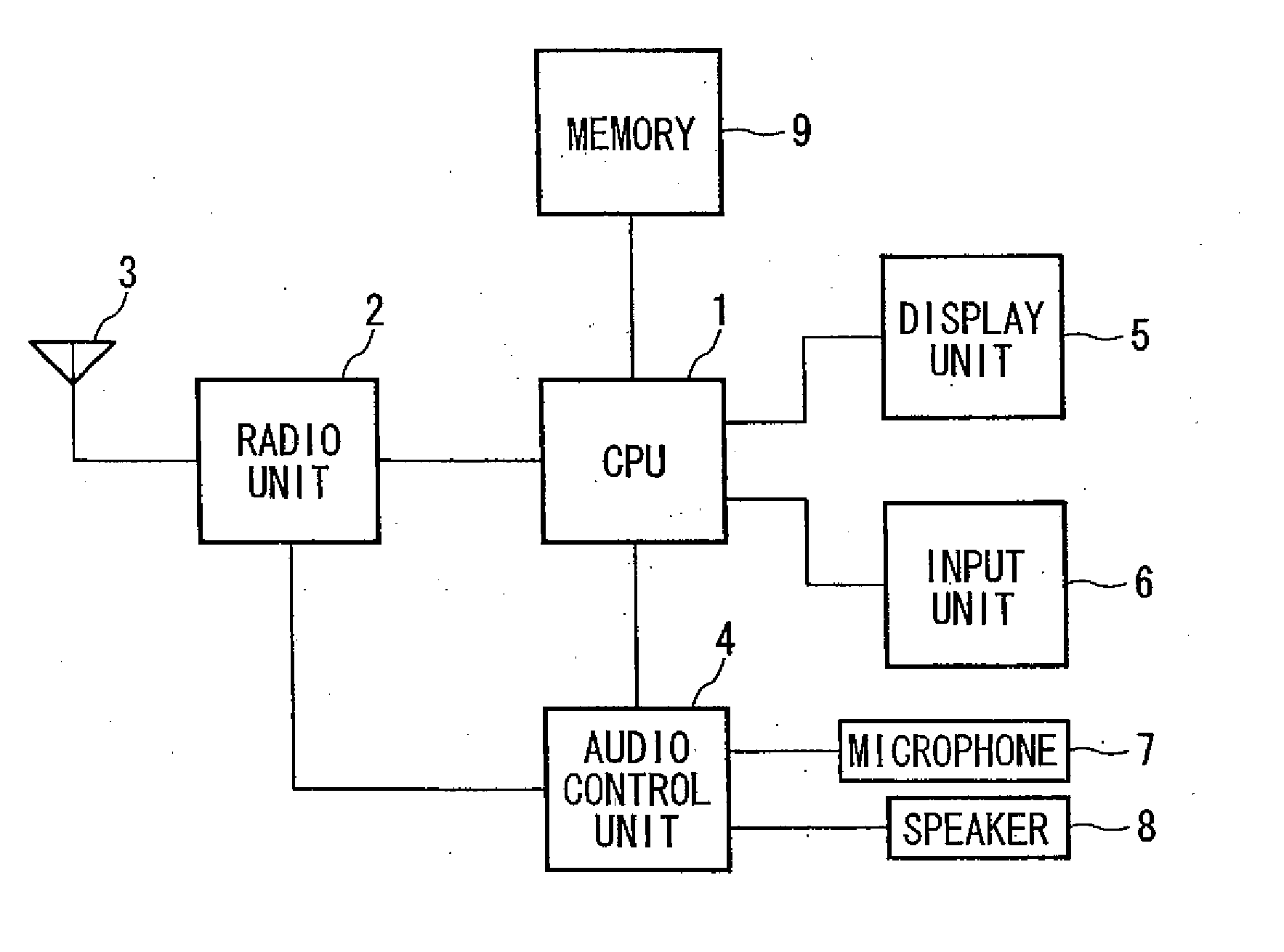
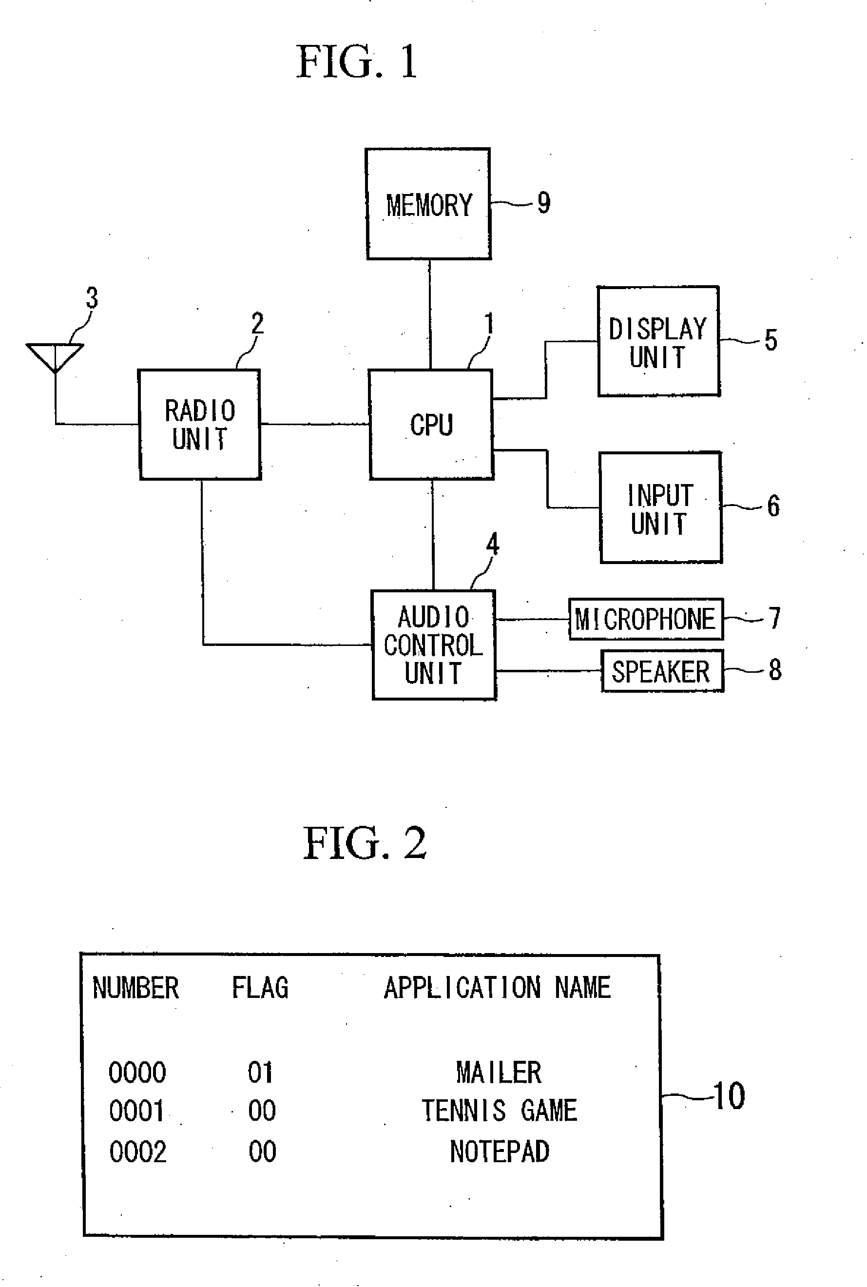
[0043] In the following, various embodiments according to a first aspect of the present invention will be explained with reference to the drawings. FIG. 1 is a block diagram illustrating a structure of a mobile telephone terminal, as an example of a mobile terminal according to the first aspect of the present invention. This mobile telephone terminal is controlled by a CPU 1, and includes a radio unit 2, an antenna 3, an audio control unit 4, a display unit 5, an input unit 6, a microphone 7, a speaker 8, and a memory 9. The antenna 3 is connected to the radio unit 2, and sends to and receives from a base station a radio signal. The received signal is handled by the audio control unit 4, and a corresponding sound is then output from the speaker 8. An audio signal input from the microphone 8 is sent to the radio unit 2 via the audio control unit 4, and sent to the base station via the antenna 3. The memory 9 stores application programs, input data, telephone numbers and email address...

second embodiment

[0051] Next, the first aspect of the present invention will be explained with reference to the flowchart of FIG. 7.

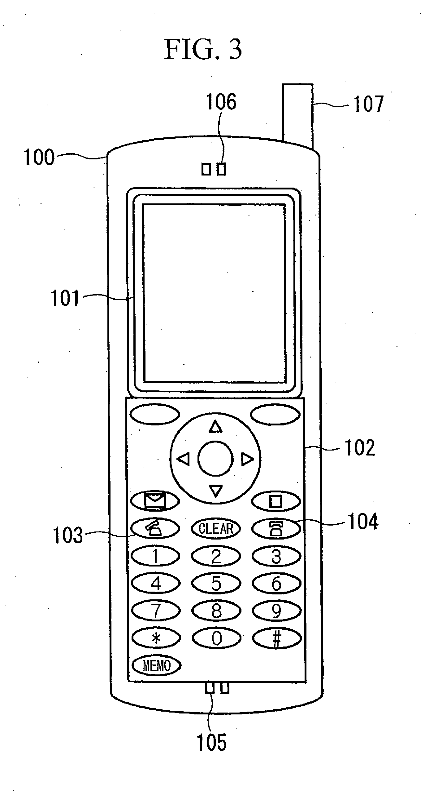
[0052] It is notified that a new application was started while an application is executed in step S501. The user selection screen 108 is displayed in step S502, and the user is prompted to choose an operation to be performed on the application that is currently displayed in step S503. When the user selects “QUIT,” the application is terminated and an entry corresponding to the terminated application is deleted from the task list 10 in step S504. If the user selects “PAUSE,” the application is paused and the flag indicating the attribute of the application is changed to “00” in the task list 10 in step S505. If the user selects “CONTINUE,” the application is continued to be executed. In the manner described above, when the user selects either “QUIT,”“PAUSE, ” or “CONTINUE” in the user selection screen 108, the new application is displayed in step S506.

[0053] According t...

third embodiment

[0054] Next, the first aspect of the present invention will be explained with reference to the flowchart of FIG. 8.

[0055] When it is notified that a new application was started while an application is executed in step S601, it is determined whether or not the current usage of the memory exceeds a certain threshold to start an application in step S602. If the current usage of the memory exceeds the threshold, the user selection screen is displayed in step S603, and the user is prompted to choose an operation to be performed on the new application in step S604. If the user selects “DO NOT START,” the start of the new application is cancelled in step S605.

[0056] If the user chooses “START,” the new application is started and added to the task list 10. After The attribute of the task list is set to “01” in step S606, the new application is displayed in step S607.

[0057] According to this embodiment, when a new application is started while an application is executed, the user is prompte...


PUM


Abstract

A mobile terminal that can execute a plurality of application programs in parallel, including a selection unit that prompts a user to select whether or not to quit an application program when a screen of the application program that is displayed is being switched to a screen of another application program.

Description

BACKGROUND OF THE INVENTION [0001] 1. Field of the Invention [0002] The present invention relates to a mobile terminal, such as a mobile telephone terminal, that can execute multiple application programs in parallel. The present invention also relates to a method for controlling a mobile telephone terminal and a mobile telephone terminal that can execute multiple application programs, including a program that handles a telephone function, and can display an application program that is running on a screen. [0003] Priority is claimed on Japanese Patent Application Nos. 2004-18342 and 2004-18343, filed Jan. 27, 2004, the contents of which are incorporated herein by reference. [0004] 2. Description of Related Art [0005] A conventional mobile telephone terminal that can execute multiple application programs (hereinafter referred to as “application”), including an application that handles a telephone function, has a very small display area due to the size constraints of mobile terminals. ...

Claims


Application Information

Patent Timeline
Patent Type & Authority Applications(United States)
IPC IPC(8): H04Q7/20H04B1/40H04M1/72469A63F13/00H04M1/00H04M1/72448H04M1/72472H04M3/00H04Q7/32
CPCH04M1/6041H04M1/72586H04M1/72583H04M1/72472H04M1/72469A63H3/08A63H33/00B42D15/02G09F3/10B31D1/02Y10S446/901
Inventor SATAKE, MASAOMI
Owner KYOCERA CORP
Learn More