Communication apparatus, transmission apparatus and reception apparatus

Inactive Publication Date: 2008-11-04
SONY CORP
View PDF6 Cites 104 Cited by
  • Summary
  • Abstract
  • Description
  • Claims
  • Application Information

AI Technical Summary

Benefits of technology

[0019]It is thus an object of the present invention, addressing the problems described above, to provide a communication apparatus capable of maintaining a high streaming quality without regard t

Problems solved by technology

However, the conventional communication apparatus has a problem in that it is difficult to maintain a streaming quality for some states of the conventional communication apparatus serving as a host.
In addition, the conventional communication apparatus has another problem in that it is hard to make the scale of the circuit compact in order to maintain a predetermined streaming quality.
For the reason described above, in dependence on the processing state of the host or the condition of the network, it may be impossible to assure sufficient precision for a measured packet arrival time or for a determined timing to pass real-time data to a protocol at a higher level.
Thus, if the reception process is entirely carried out by using software, in some cases, sufficient precision cannot be assured because of reasons such as the fact that the measured time and the determined timing lag behind their respective correct values.
If the measured arrival time has a lack of precision, it is impossible to estimate a QoS (Quality of Service) on the network with a high degree of accuracy.
Thus, information cannot b

Method used


Image

  • Communication apparatus, transmission apparatus and reception apparatus
  • Communication apparatus, transmission apparatus and reception apparatus
  • Communication apparatus, transmission apparatus and reception apparatus

Examples


second embodiment

[0113]As described above, in the present invention, when the transmission-side RTP timer 131 is not synchronized with the reception-side RTP timer 132, the value of the reception-side RTP timer 132 is automatically corrected to eliminate the discrepancy. As a result, the synchronization between the transmission-side RTP timer 131 and the reception-side RTP timer 132 can be assured so as to sustain the streaming stability and the streaming high quality.

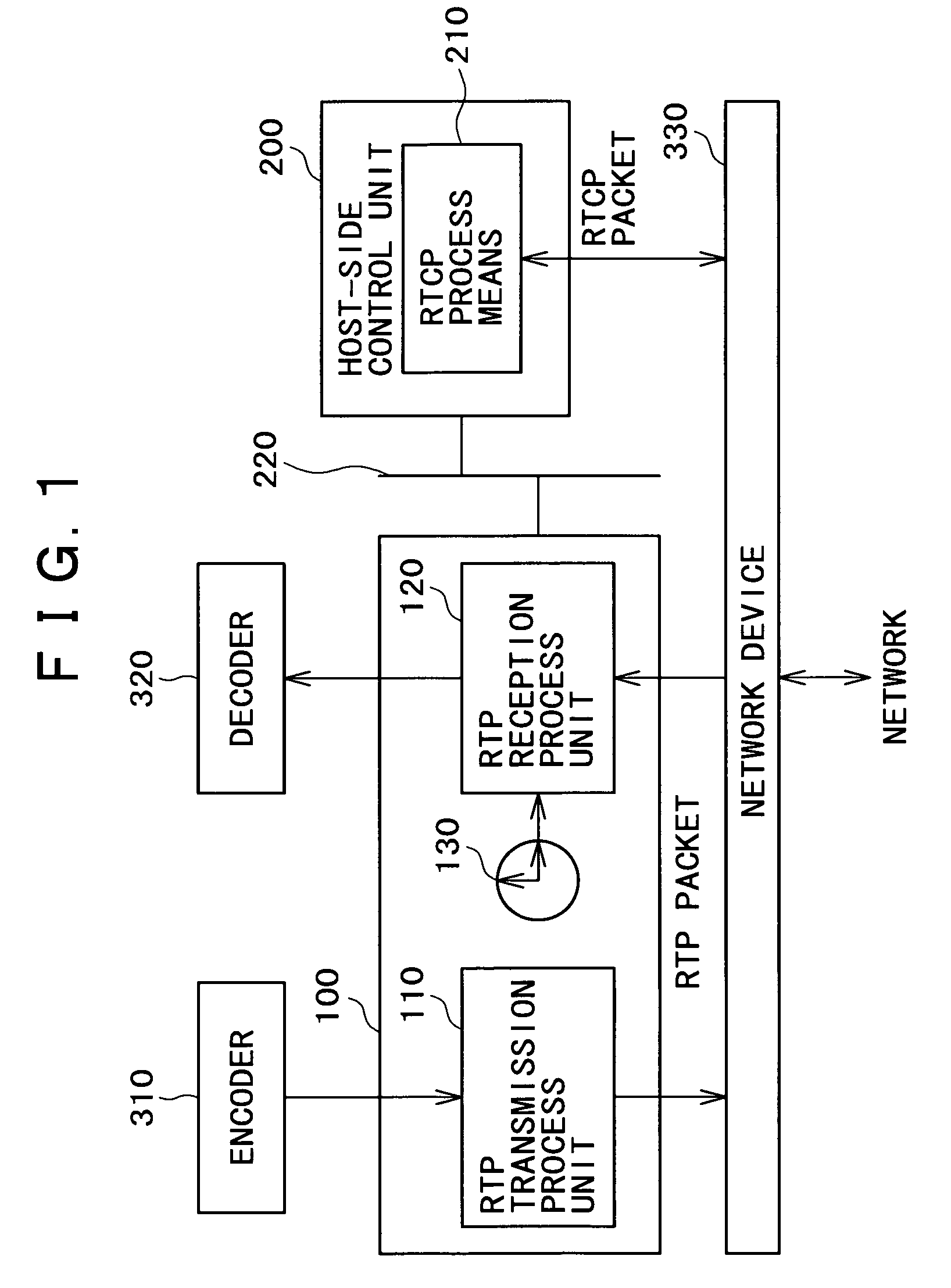
[0114]In addition, in general, when the communication system is started up from an initial state, the transmission-side communication apparatus 101 and the reception-side communication apparatus 102 carry out a process to synchronize the transmission-side RTP timer 131 with the reception-side RTP timer 132. Thus, in the communication apparatus provided by the present invention, the RTP reception process unit 120 is capable of measuring the arrival time of an RTP packet with a high degree of precision. By utilizing this measured arrival...

third embodiment

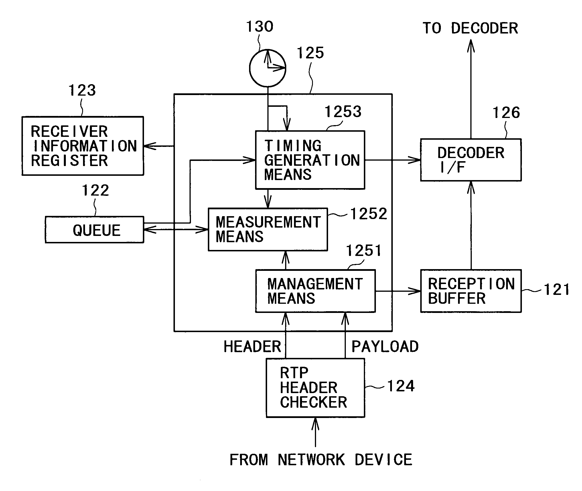
[0115]FIG. 7 is a block diagram showing the configuration of an RTP reception process unit employed in a communication apparatus implemented by the present invention. Components identical with their counterparts shown in FIG. 4 are denoted by the same reference numerals as the counterparts.

[0116]The RTP reception process unit employed in a communication apparatus implemented by the third embodiment further has a time information generation means 128 in addition to the components employed in the RTP reception process unit 120 shown in FIG. 4.

[0117]In the case of the third embodiment, the reception-side RTP timer 132 has a clock oscillator 1321 for generating an original clock signal with a predetermined frequency and a frequency divider 1322 for generating another clock signal with a desired frequency by dividing the predetermined frequency of the original clock signal.

[0118]The time information generation means 128 includes a timer initialization means 1281, a timestamp initial valu...

fourth embodiment

[0145]Much like the packet transmission controller 1131 employed in the fourth embodiment shown in FIG. 8, the packet transmission controller 1115 manages boundaries used in mapping TS packets onto an RTP payload in the TS buffer 112a on the basis of information received from the TS header checker 1111. As soon as conditions are altogether satisfied, the packet transmission controller 1115 writes a request to transmit transmission control information of an RTP packet into the TS buffer 112a. The packet synthesizer 1132 is monitoring the TS buffer 112a to detect a request for a transfer of an RTP packet to the network device 330 in the transmission control information. As such a request is detected, the RTP packet is transferred to the network device 330 in accordance with the transmission control information stored in the TS buffer 112a.

[0146]The following description explains buffering and writing operations carried out by each of the packet transmission controller 1115, the TS da...


PUM


Abstract

Upon reception of a transport stream of information data from an encoder, an RTP transmission process unit employed in an RTP process circuit is activated to packetize the transport stream in an RTP packet. A network device then outputs the resulting RTP packet to a network. At that time, sender information for the transmission is created and stored. On the other hand, an RTP reception process unit employed in the RTP process circuit depacketizes an RTP packet received from the network through the network device to obtain a transport stream and supplies the transport stream to a decoder. At that time, receiver information for the reception is created and stored. An RTCP process means employed in a control unit on the host side acquires the sender information and the receiver information through an internal bus and uses them to create an RTCP packet to be output to the network by way of the network device. As a result, the streaming quality can be assured independently of the state of the control unit on the host side.

Description

BACKGROUND OF THE INVENTION[0001]The present invention relates to a communication apparatus, a transmission apparatus and a reception apparatus. More particularly, the present invention relates to a communication apparatus, a transmission apparatus and a reception apparatus, which are used for transmitting and receiving streaming data to and from a network.[0002]In the past, some transmission protocols were proposed suitable for transferring video data including moving-picture data, audio data and auxiliary data to a destination by way of a network and streaming to reproduce the data in a real-time manner. The RFC 1889 has recommended an RTP (Real-time Transport Protocol), which is one of the proposed transmission protocols, as a transport protocol for realizing a real-time transport application for transmitting / receiving sounds and moving pictures in a real-time manner by way of an IP network such as the Internet.[0003]In general, the RTP is adopted in conjunction with an RTCP (Rea...

Claims


Application Information

Patent Timeline
IPC IPC(8): H04L1/00H04L49/9023
CPCH04L47/10H04L47/2416H04L47/28H04L47/431
Inventor UEDA, SATOSHIYOSHIDA, HIDEKI
Owner SONY CORP
Why Eureka
Try Eureka