Radio receiving apparatus, mobile station appartus, base station apparatus, and radio receiving method

a radio receiving and mobile station technology, applied in the direction of orthogonal multiplex, pulse technique, baseband system details, etc., can solve the problems of increasing the circuit can be reduced, so as to reduce the circuit scale of the overall receiving section, reduce the size and cost of the apparatus, and reduce the overall apparatus. the effect of the circuit scal

Inactive Publication Date: 2006-12-07
PANASONIC CORP
View PDF5 Cites 44 Cited by
  • Summary
  • Abstract
  • Description
  • Claims
  • Application Information

AI Technical Summary

Benefits of technology

[0010] It is an object of the present invention to provide a radio receiving apparatus and radio receiving method that enable the overall apparatus circuit scale to be reduced, and small apparatus size and low apparatus cost to be achieved, without increasing the processing load, together with a mobile station apparatus and base station apparatus equipped with this radio receiving apparatus.

Problems solved by technology

However, a problem with the above-described conventional radio receiving apparatus is that, although the circuit scale of the overall receiving section including the receiving antennas and receiving RF circuits can be reduced, it is necessary to newly provide other circuitry such as interpolation circuitry for each receiving antenna.
The increase in circuit scale leads to increased apparatus size and cost.

Method used


Image

  • Radio receiving apparatus, mobile station appartus, base station apparatus, and radio receiving method
  • Radio receiving apparatus, mobile station appartus, base station apparatus, and radio receiving method
  • Radio receiving apparatus, mobile station appartus, base station apparatus, and radio receiving method

Examples


embodiment 1

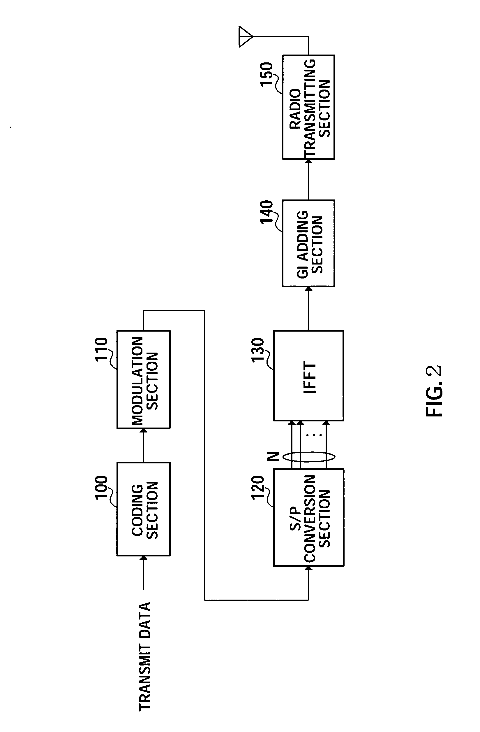
[0047]FIG. 2 is a block diagram showing the configuration of a radio transmitting apparatus used in Embodiment 1 of the present invention. The radio transmitting apparatus shown in FIG. 2 has a coding section 100, a modulation section 110, an S / P (Serial-Parallel) conversion section 120, an IFFT section 130, a GI (Guard Interval) adding section 140, and a radio transmitting section 150.

[0048] Transmit data undergoes error correction coding by coding section 100 and is modulated by modulation section 110. The modulated data then undergoes S / P conversion by S / P conversion section 120 and N streams of parallel data are output.

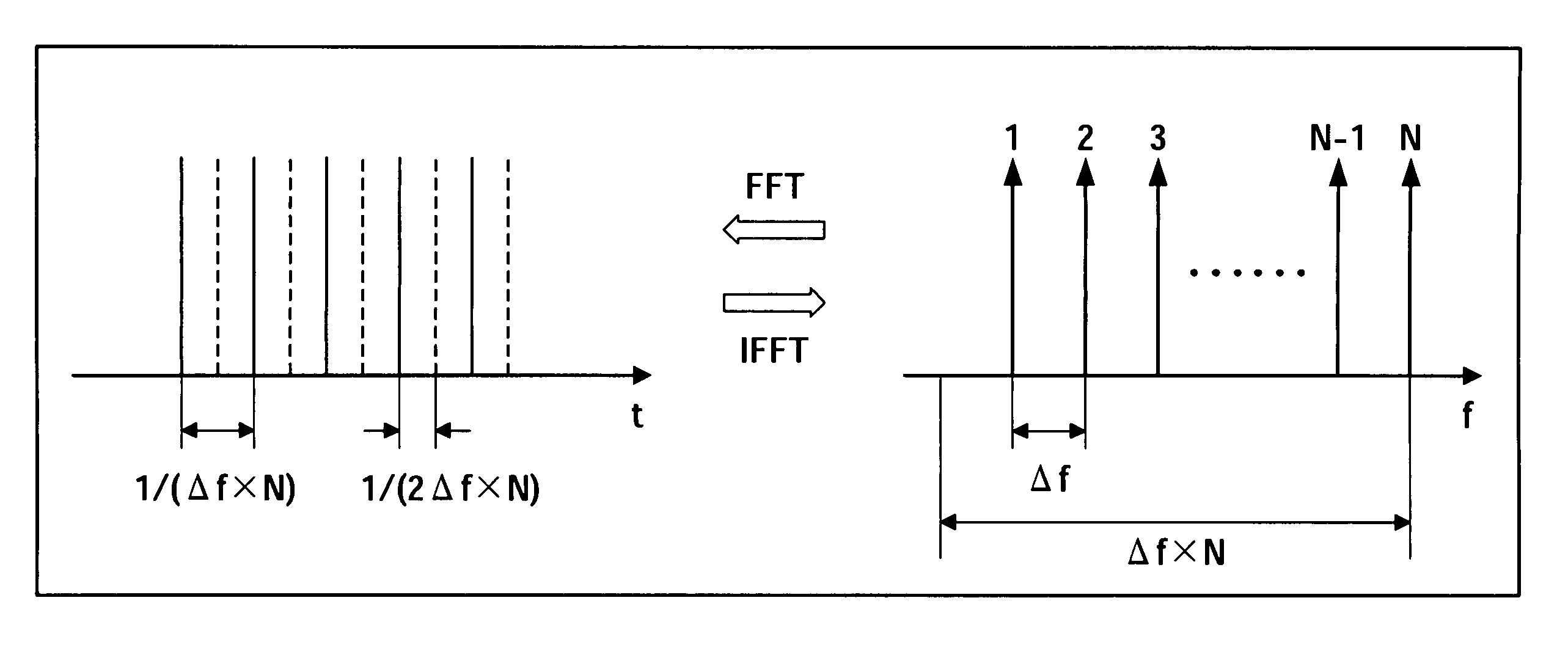
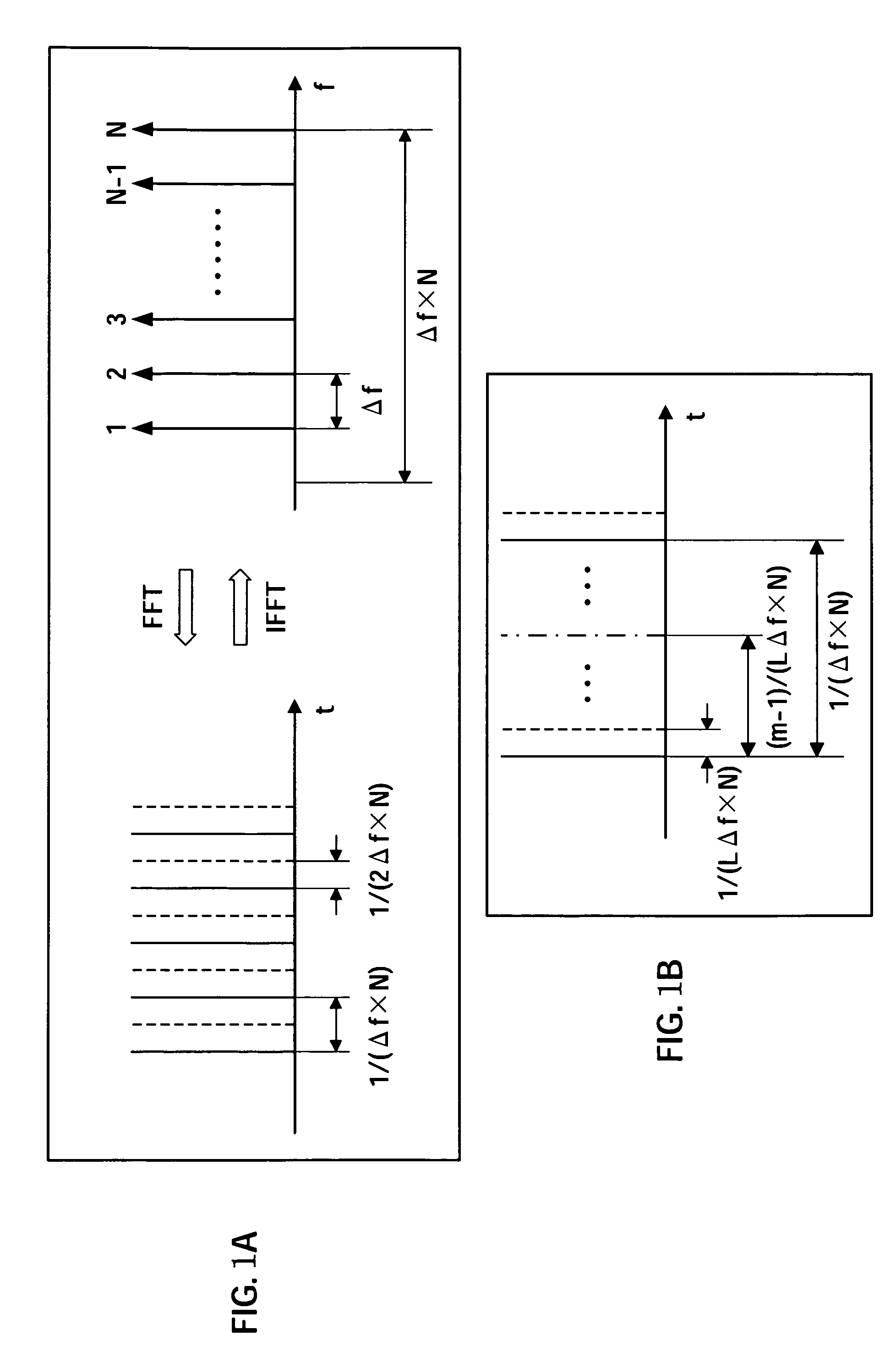
[0049] The N streams of parallel data undergo inverse fast Fourier transform processing by IFFT section 130, and the data of the corresponding streams are superimposed on N mutually orthogonal subcarriers. A guard interval to prevent inter-symbol interference is then added by GI adding section 140, and an OFDM signal is generated.

[0050] The generated OFDM signa...

embodiment 2

[0079] A feature of Embodiment 2 of the present invention is that phase rotation due to a difference in sampling timings is performed at the same time as channel estimation phase rotation.

[0080] The configuration of a radio transmitting apparatus used in this embodiment is the same as in Embodiment 1 (FIG. 2), and therefore a description thereof is omitted.

[0081]FIG. 4 is a block diagram showing the configuration of a radio receiving apparatus according to this embodiment. Parts of the radio receiving apparatus shown in FIG. 4 identical to those of the radio receiving apparatus shown in FIG. 4 are assigned the same codes as in FIG. 3 and descriptions thereof are omitted. A radio receiving apparatus according to this embodiment is used installed in a mobile station apparatus or base station apparatus in a mobile communication system.

[0082] The radio receiving apparatus shown in FIG. 4 has a switch 200, a radio receiving section 210, a switch 220, GI removing sections 230-1 and 230...

embodiment 3

[0097] A feature of Embodiment 3 of the present invention is that a radio receiving apparatus of the present invention is used in a mobile communication system that uses the CDMA method.

[0098]FIG. 5 is a block diagram showing the configuration of a radio transmitting apparatus used in this embodiment. Parts of the radio transmitting apparatus shown in FIG. 5 identical to those of the radio transmitting apparatus shown in FIG. 2 are assigned the same codes as in FIG. 2 and detailed descriptions thereof are omitted. The radio transmitting apparatus shown in FIG. 5 has a coding section 100, a modulation section 110, a spreading section 400, an S / P conversion section 120, an IFFT section 130, a GI adding section 140, and a radio transmitting section 150.

[0099] Transmit data that has undergone error correction coding by coding section 100 and has been modulated by modulation section 110 is spread by spreading section 400 using a predetermined spreading code. The spread data then underg...


PUM


Abstract

A radio receiving apparatus and radio receiving method are provided that enable the overall apparatus circuit scale to be reduced, and small apparatus size and low apparatus cost to be achieved, without increasing the processing load, together with a mobile station apparatus and base station apparatus equipped with this radio receiving apparatus. A phase control section (290) holds a phase rotation amount of each subcarrier signal due to the delay in the sampling timing of the second antenna with respect to the first antenna, decided in advance according to the number of antennas of the radio receiving apparatus and the subcarrier frequencies. The phase control section (290) performs phase rotation by the held phase rotation amount of each of N subcarrier signals output from an FFT section (240-2) corresponding to the second antenna.

Description

TECHNICAL FIELD [0001] The present invention relates to a radio receiving apparatus, mobile station apparatus, base station apparatus, and radio receiving method, and more particularly to a radio receiving apparatus and radio receiving method having a plurality of receiving antennas for diversity reception and adaptive array reception. BACKGROUND ART [0002] In recent years, the use of OFDM (Orthogonal Frequency Division Multiplexing) in radio communication systems has been studied. OFDM is a technology whereby signals are superimposed on a plurality of subcarriers whose frequencies are mutually orthogonal, and has the advantages of improving frequency utilization and being highly resistant to multipath interference. OFDM is mainly used in digital broadcasting and WLANs (Wireless Local Area Networks), and is expected to be used in a wider range of application areas in the future. [0003] While OFDM offers high frequency utilization and good resistance to multipath interference, as sta...

Claims


Application Information

Patent Timeline
Patent Type & Authority Applications(United States)
IPC IPC(8): H04L27/12H04J11/00H04B1/707H04B1/7115H04B7/02H04B7/08H04L1/02H04L25/02H04L27/26
CPCH04B7/0805H04B7/084H04L27/2647H04L25/022H04B7/0894
Inventor MATSUMOTO, ATSUSHIMIYOSHI, KENICHI
Owner PANASONIC CORP
Why Eureka
Try Eureka