Light control apparatus and optical apparatus

a control apparatus and optical technology, applied in the field of light control apparatus, can solve the problems of increasing the number of components, reducing the number of stops, so as to increase the number of stops and reduce the overall size of the apparatus

Inactive Publication Date: 2006-04-13
CANON KK
View PDF6 Cites 9 Cited by
  • Summary
  • Abstract
  • Description
  • Claims
  • Application Information

AI Technical Summary

Benefits of technology

[0007] The present invention is directed to a light control apparatus that maintains the overall apparatus size small, increases the number of stop stages, and is suitable for both the shutter and stop actions.

Problems solved by technology

However, the above conventional stop-cum-shutter unit in which one motor drives two stop-cum-shutter blades and forms an aperture has difficulties in making the aperture shape circular and making the stop multistage.
However, use of the ring member increases the number of components, and makes the apparatus large.
In addition, the stepping motor is unsuitable for quick shutter actions of plural stop blades connected to the ring member.
It is therefore difficult to form a suitable structure for both the stop action and the shutter action.

Method used


Image

  • Light control apparatus and optical apparatus
  • Light control apparatus and optical apparatus
  • Light control apparatus and optical apparatus

Examples


first embodiment

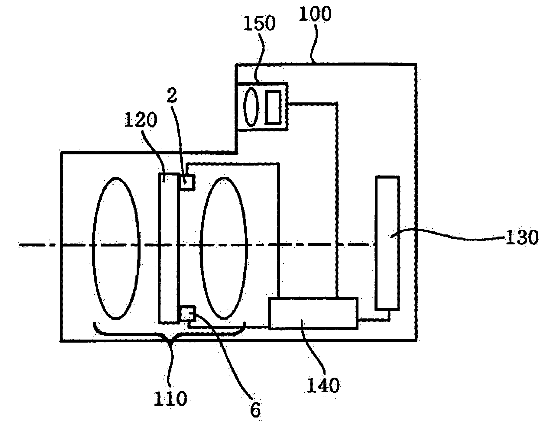
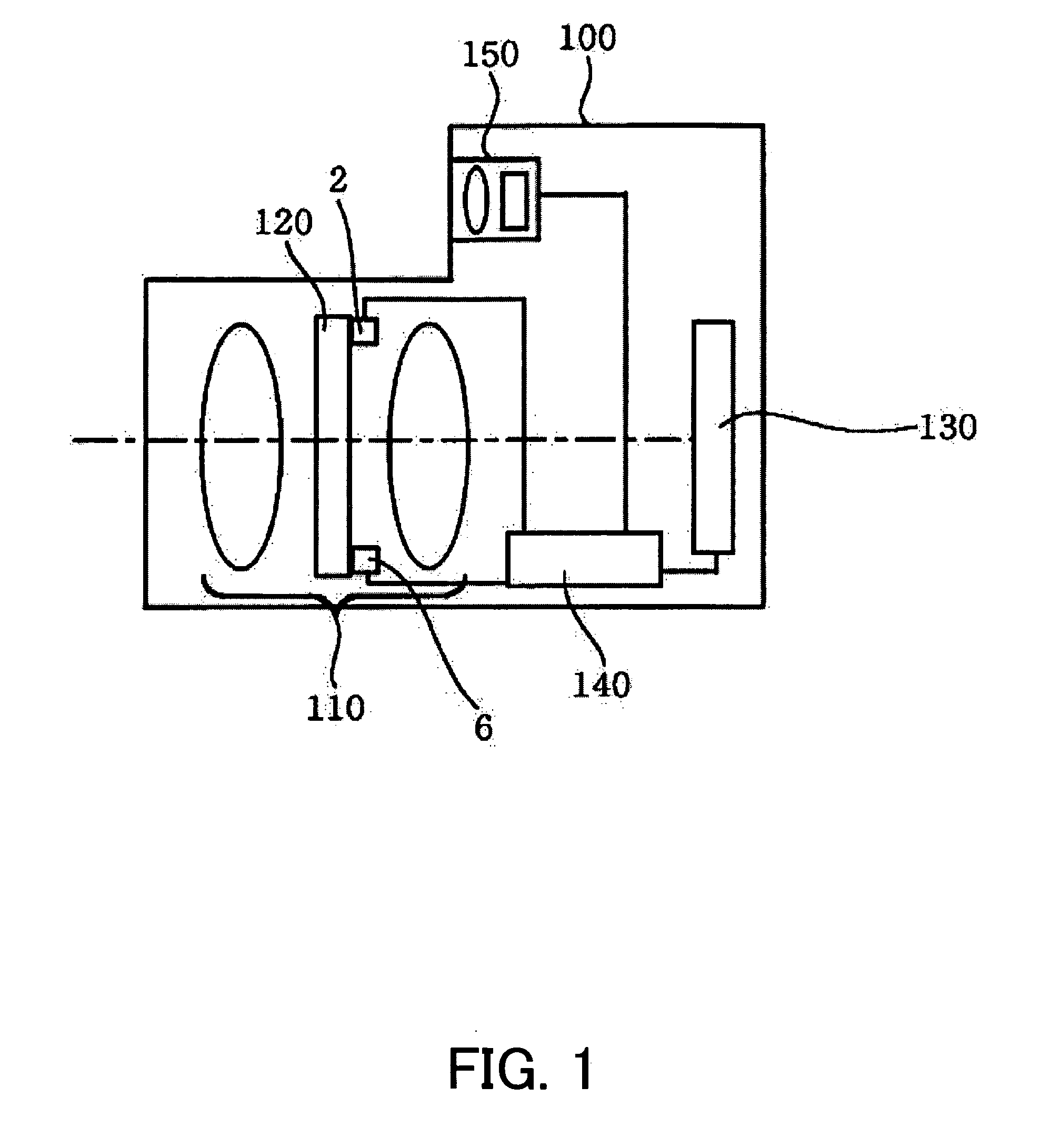
[0030]FIG. 1 shows a schematic structure of a digital still camera having a light control apparatus according to a first embodiment of the present invention. In FIG. 1, 100 denotes a camera body, and 110 denotes an image-taking optical system. The light control apparatus 120 is provided in the image-taking optical system 110. 130 denotes an image-pickup device or an image sensor, such as a CCD sensor and a CMOS sensor, and photoelectrically converts a subject image formed by the image-taking optical system 110. An image processing control circuit 140 performs various processes for an output signal from the image-pickup device 130, and generates a shot image. The data of the shot image is recorded in a recording medium (not shown), such as a semiconductor memory, a magnetic disc, and an optical disc.

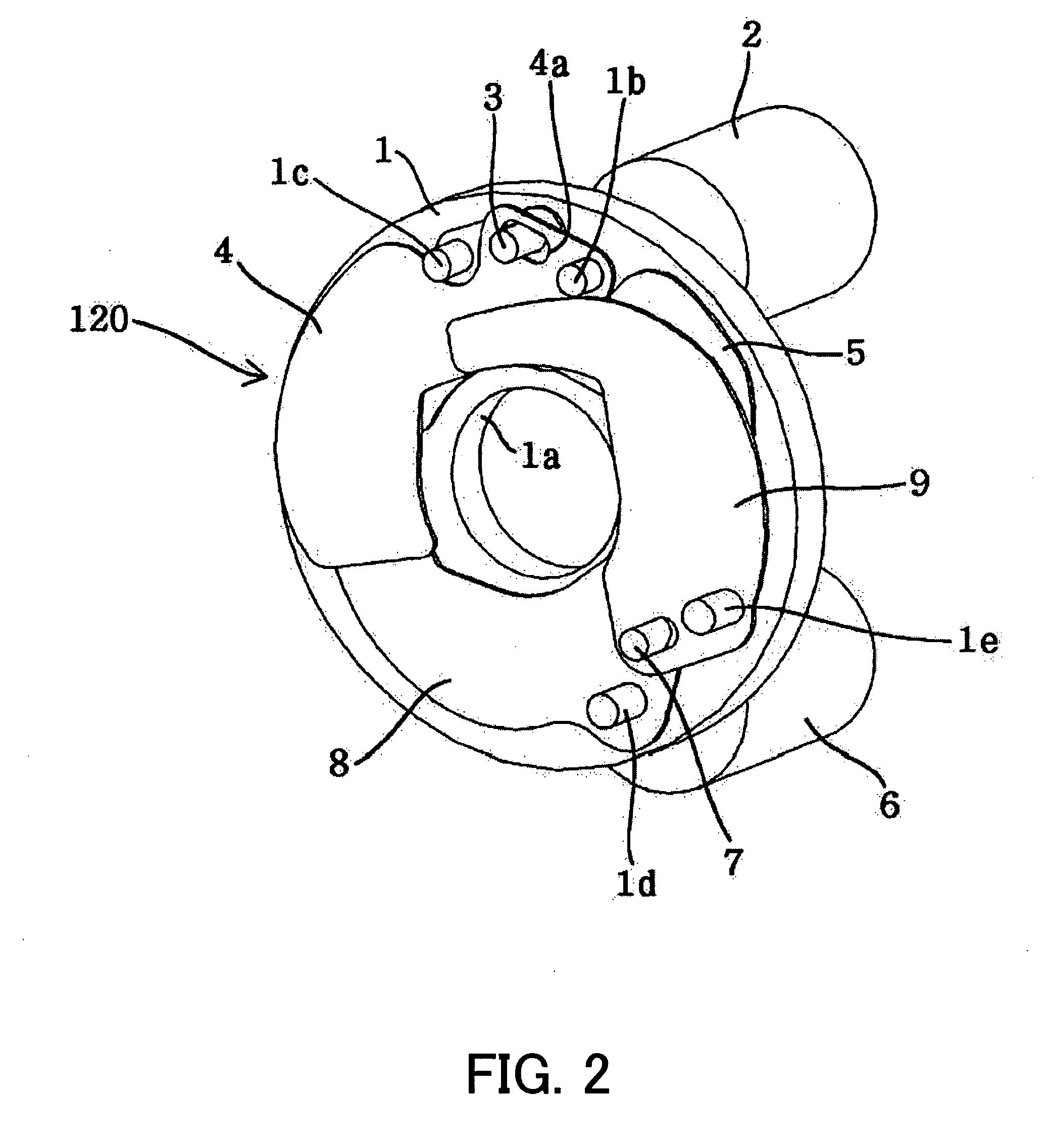
[0031]FIGS. 2 and 3 show a light control apparatus 120 as a stop-cum-shutter apparatus according to this embodiment.

[0032]1 denotes a base plate having a release opening 1a at its cente...

second embodiment

[0047]FIGS. 9 and 10 show a structure of the light control apparatus 220 as a stop-cum-shutter unit according to a second embodiment of the present invention. The light control apparatus 220 of this embodiment is provided in an image-taking optical system in the camera, as in the first embodiment.

[0048]11 denotes a base plate having a release opening 11a at its center thereof. A stepping motor (or first actuator) 12 is held above the base plate 11, and a rotation of the stepping motor 2 is transmitted to blades 14 (or fist light shielding members) 14 and 15 via a driving lever 13.

[0049] The blade 14 has two contact parts 14a and 14b. The contact part 14a has such a convex shape at the side of the base plate 11 that the contact part 14a contacts an outer circumference part of the blade 18. The contact part 14b has such a convex shape at a side opposing to the base plate 11 that the contact part 14b contacts an outer circumference part of the blade 19. This embodiment that provides ...


PUM


Abstract

There is provided a light control apparatus that maintains the overall apparatus size small, increases the number of stop stages, and is suitable for both the shutter and stop actions. A light control apparatus includes a first actuator, a second actuator, a first light shielding member driven by the first actuator, and a second light shielding member driven by the second actuator, wherein in a stop adjusting action, the first and second actuators drive the first and second light shielding members and adjust an aperture formed by the first and second light shielding members, and wherein in a shutter action, the second actuator drives the second light-shielding member for a light shielding action.

Description

BACKGROUND OF THE INVENTION [0001] The present invention relates to a light control apparatus for a stop-cum-shutter to be mounted in an optical apparatus, such as a still camera, a video camera and an interchangeable lens. [0002] As an optical apparatus, such as a digital camera, has been made smaller, a smaller shutter unit and a smaller stop unit are required to be mounted on it. A light control apparatus (shutter-cum-stop unit) is known which serves as both a shutter and a stop, and makes the optical apparatus smaller than a combination of a shutter unit and a stop unit separately. [0003] Japanese Patent Application, Publication No. 2002-55375 discloses a stop-cum-shutter unit that includes a pair of motors, and a pair of stop-cum-shutter blades driven by these motors. As one motor is electrified, the stop-cum-shutter unit drives both stop-cum-shutter blades to a position that forms a predetermined aperture. As the other motor is electrified while the stop state is maintained, b...

Claims


Application Information

Patent Timeline
Patent Type & Authority Applications(United States)
IPC IPC(8): G03B9/08
CPCG03B9/06G03B9/10G03B9/24
Inventor MASUDA, SHINICHI
Owner CANON KK
Why Eureka
Try Eureka