Digital image output method

a digital image and output method technology, applied in the direction of digital output to print units, instruments, computing, etc., can solve the problems of high cost of the central output center, inability to achieve real-time service, and inability to meet the customer's demand for the speed of developing and printing, etc., to achieve enhanced image output efficiency, reduce apparatus cost, and increase image output speed effectively

Inactive Publication Date: 2006-05-18
AVISION
View PDF6 Cites 0 Cited by
  • Summary
  • Abstract
  • Description
  • Claims
  • Application Information

AI Technical Summary

Benefits of technology

[0007] It is therefore an object of the invention to provide a digital image output method capable of smartly distributing image outputting tasks to several output modules via a control center so as to increase the image output speed effectively with the low apparatus cost. Thus, it is unnecessary to send the images to the central output center, and the store can process the images and print the photos with an enhanced image output efficiency.

Problems solved by technology

Thus, the conventional method cannot satisfy the customer's demand on the speed of developing and printing and cannot achieve the real time service.
In addition, because the system in the central output center 130 is very expensive, the ordinary consumer cannot afford to pay the fee.

Method used


Image

  • Digital image output method
  • Digital image output method
  • Digital image output method

Examples


Embodiment Construction

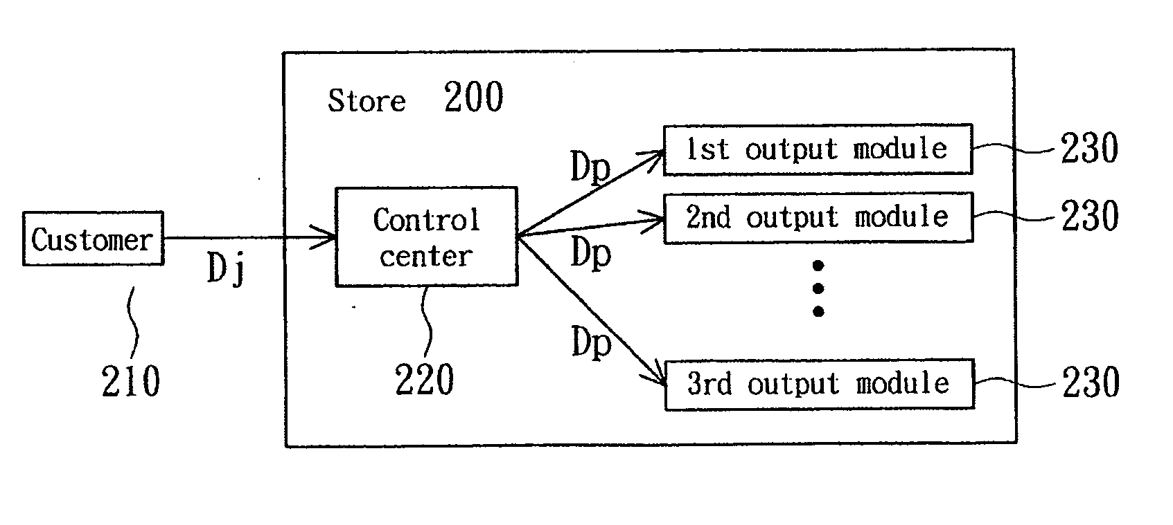
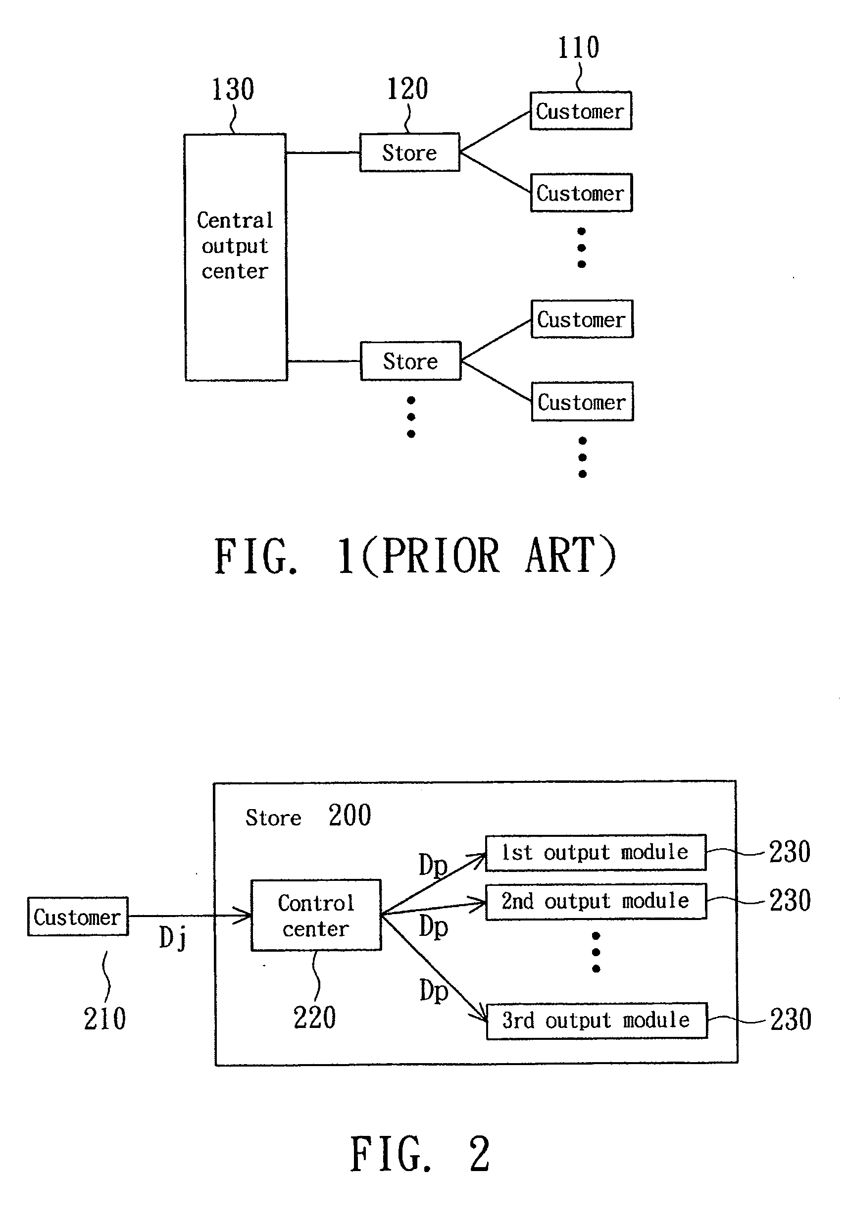
[0013]FIG. 2 is a block diagram showing a digital image output architecture according to a preferred embodiment of the invention. The store 200 inputs p sets of digital image data Dd, such as photograph images or invoice images, sent from the customer 210, to the control center (e.g., a computer host) 220 for processing the images, wherein p is a positive integer greater than 1. Then, the control center 220 distributes the processed image data Dp to n output modules 230, such as inkjet printers, for print and output, wherein n is a positive integer greater than 1, and n is 15 in this example.

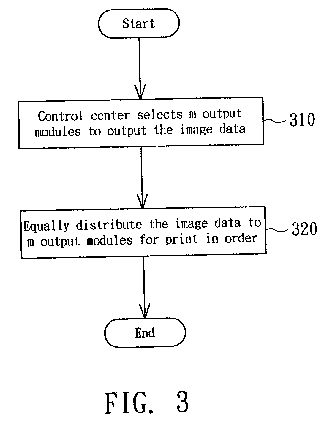
[0014]FIG. 3 is a flow chart showing a digital image output method according to a preferred embodiment of the invention. First, step 310 selects m output modules 230 to output the image data via the control center 220 according to the setting of the store 200, wherein m is a positive integer, such as 15, greater than 1 and smaller than or equal to n. Next, step 320 equally distributes the p (e....


PUM


Abstract

A digital image output method includes the steps of selecting a number of output modules to output image data via a control center, and equally distributing the image data to the selected output modules for print in order.

Description

[0001] This application claims the benefit of Taiwan application Serial No. 93135500, filed Nov. 18, 2004, the subject matter of which is incorporated herein by reference. BACKGROUND OF THE INVENTION [0002] 1. Field of the Invention [0003] The invention relates in general to a digital image output method, and more particularly to a digital image output method of smartly distributing multiple image output tasks to multiple printing modules. [0004] 2. Description of the Related Art [0005] With the coming of the digital image age, the conventional photography labs have gradually transformed into digital photography labs in order to satisfy the increasing demands of users on the digital images and provide a convenient digital image output channel. [0006]FIG. 1 is a schematic block diagram showing a conventional digital image output procedure. As shown in FIG. 1, when a customer 110 asks for a store 120 (i.e., digital photography lab) to develop the film and print the photos, the store 1...

Claims


Application Information

Patent Timeline
Patent Type & Authority Applications(United States)
IPC IPC(8): G06F3/12
CPCG06F3/1204G06F3/1215G06F3/124G06F3/1288
Inventor WU, YUNG-CHUANWANG, BO-HSIANG
Owner AVISION
Why Eureka
Try Eureka