Impact mechanism for a hammer drill

a technology of impact mechanism and hammer drill, which is applied in the field of impact mechanism of hammer drill, can solve the problems of unsatisfactory high output speed, efficiency loss, and tendency to produce a “skipping effect”

Active Publication Date: 2006-05-18
THE HONG KONG POLYTECHNIC UNIV
View PDF8 Cites 13 Cited by
  • Summary
  • Abstract
  • Description
  • Claims
  • Application Information

AI Technical Summary

Benefits of technology

[0006] It is, therefore, an object of the present invention to provide an improved impact mechanism for a hammer drill that accomplishes desired high blows per minute (BPM) without requiring an undesirable high output speed, or at least provide the public with a useful choice. SUMMARY OF THE INVENTION

Problems solved by technology

A primary disadvantage associated with existing impact mechanisms for hammer drills is the fact that in order to accomplish a desired high blows per minute (BPM) for efficient hammer drill performance, an undesirable high output speed is required.
However, an increased number of impact ramps tend to produce a “skipping” effect and efficiency loss due to the smaller area of surface contact for each ramp.

Method used


Image

  • Impact mechanism for a hammer drill
  • Impact mechanism for a hammer drill
  • Impact mechanism for a hammer drill

Examples


Embodiment Construction

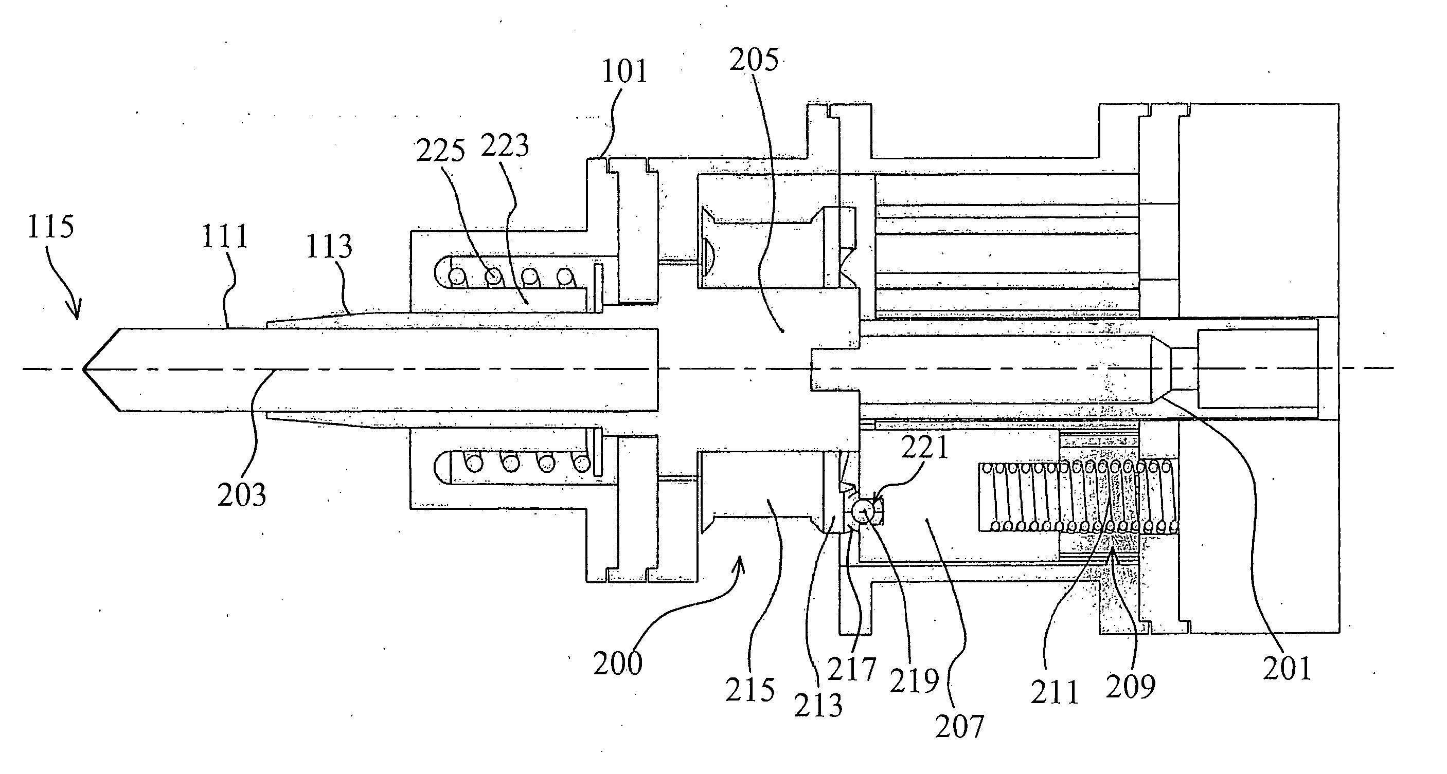
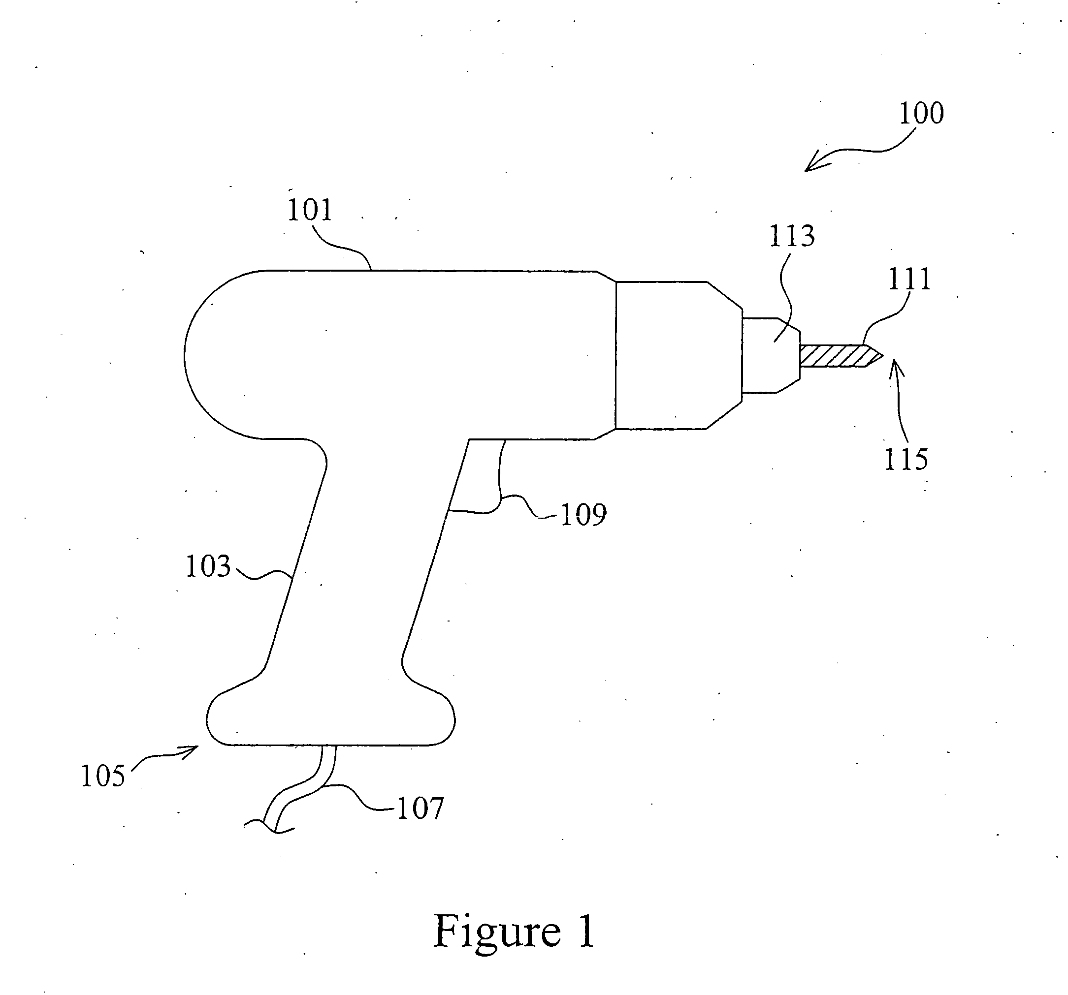
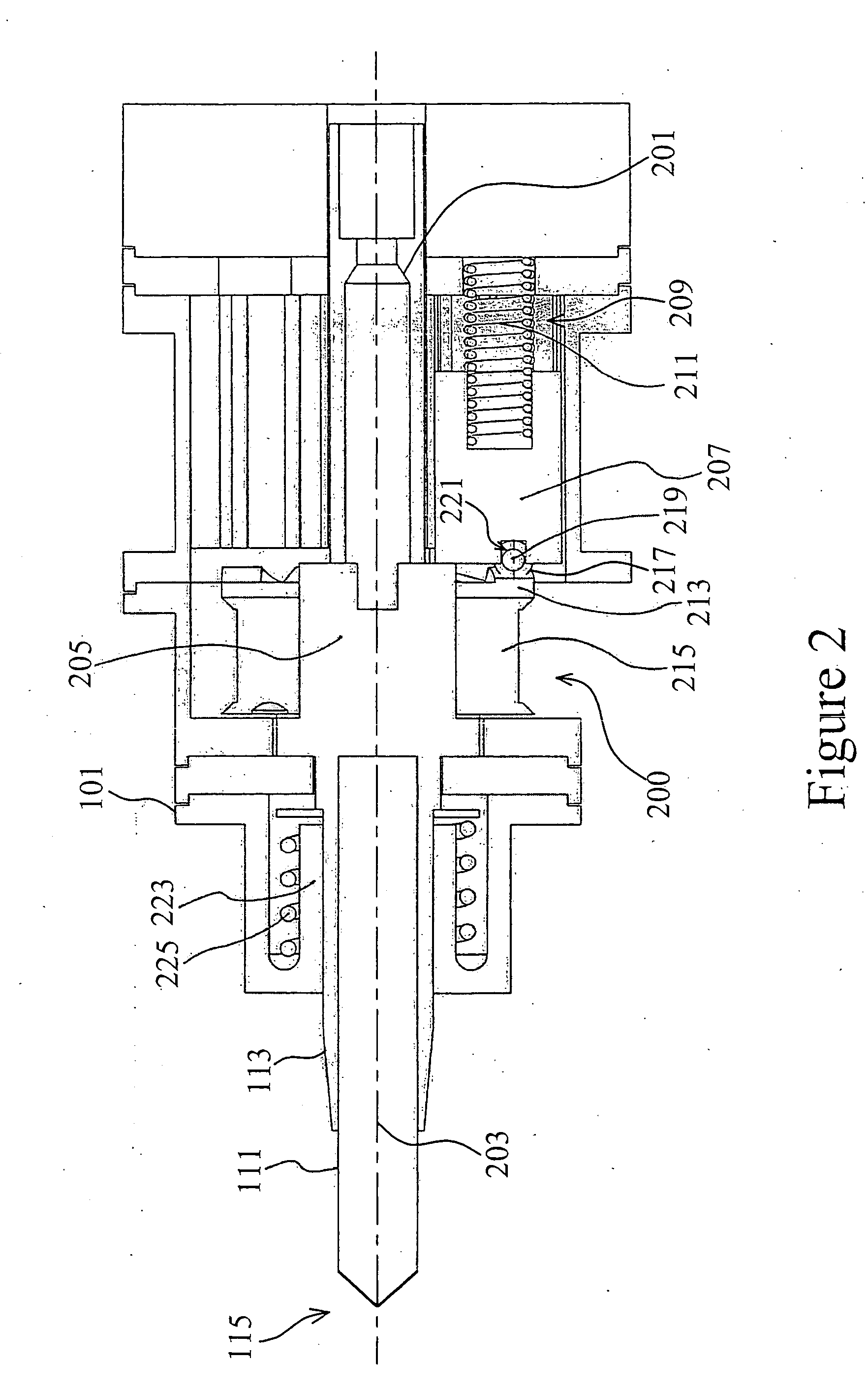
[0023] As shown in FIG. 1, an exemplary hammer drill 100 includes a housing 101 having a pistol grip handle 103. The lower end 105 of housing 101 receives an electrical cord 107. The electrical cord 107 is adapted to be connected to a suitable power source (not shown) that powers a motor (not shown) within the housing 101. In the case of a battery-powered hammer drill, the electrical cord 107 will be internal and connected to a battery instead. The cord 107 is in circuit with a trigger switch 109 on the handle 103 of housing 101. Of course, the present invention is equally useful with a battery powered cordless hammer drill. The trigger switch 109 selectively supplies power to the motor. A suitable speed control device (not shown) for controlling motor speed can also be included in a circuit connected to trigger switch 109, if so desired. A drill bit 111, protruding outside the housing 101 and held by a drill chuck 113, can be driven to rotate for drilling through a workpiece (not s...


PUM

PropertyMeasurementUnit
degrees of rotationaaaaaaaaaa
impact forcesaaaaaaaaaa
impact forceaaaaaaaaaa

Abstract

An impact mechanism for a hammer drill, which has a housing and a drill bit protruding outside the housing, is provided. The mechanism includes firstly an impact platform within the housing; the impact platform is in connection with the drill bit for receiving impact forces and for transferring the impact forces to the drill bit. The mechanism also has a plurality of cams within the housing, and the plurality of cams are angularly spaced apart and arranged about an axis of rotation. The mechanism further includes a plurality of hammers placed within the housing and interactable with both the impact platform and the plurality of cams. The plurality of hammers are angularly spaced apart and arranged about the axis of rotation, and each hammer is capable of reciprocating along the axis for exerting the impact forces on the impact platform. Each of the plurality of cam is driven to interact with each of the plurality of hammers alternatively such that the plurality of hammers are driven to reciprocate along the axis so as to generate the impact forces.

Description

BACKGROUND [0001] 1. Field of the Invention [0002] The present invention relates to hammer drills, and more particularly, to an impact mechanism for a hammer drill. [0003] 2. Background of the Invention [0004] When drilling through hard surfaces such as rocks or stone, many times it is desirable to impart a reciprocating motion to the drill bit to facilitate drilling. This hammering motion of the drill bit helps break up the material while the rotating of the drill bit allows the broken up material to be removed from the hole being drilled. [0005] A primary disadvantage associated with existing impact mechanisms for hammer drills is the fact that in order to accomplish a desired high blows per minute (BPM) for efficient hammer drill performance, an undesirable high output speed is required. High BPM can also be achieved by increasing the number of ramps on the impact mechanism. However, an increased number of impact ramps tend to produce a “skipping” effect and efficiency loss due t...

Claims


Application Information

Patent Timeline
Patent Type & Authority Applications(United States)
IPC IPC(8): B25D9/00
CPCB25D11/102B25D16/00B25D2211/064
Inventor YUNG, KAI-LEUNG
Owner THE HONG KONG POLYTECHNIC UNIV
Why Eureka
Try Eureka