

Slanted-slot type precise piezoelectric stick-slip linear motor and driving method thereof
A linear motor and chute technology, applied in the field of micro-nano precision drive and positioning, can solve the problems of zigzag-like uneven motion output, difficulty in comprehensive control of friction force, limited output mechanical performance, etc., to improve mechanical output characteristics, The effect of reducing the displacement back-off rate and improving the output efficiency
- Summary
- Abstract
- Description
- Claims
- Application Information
AI Technical Summary
Problems solved by technology
Method used
Image

Examples
specific Embodiment approach 1
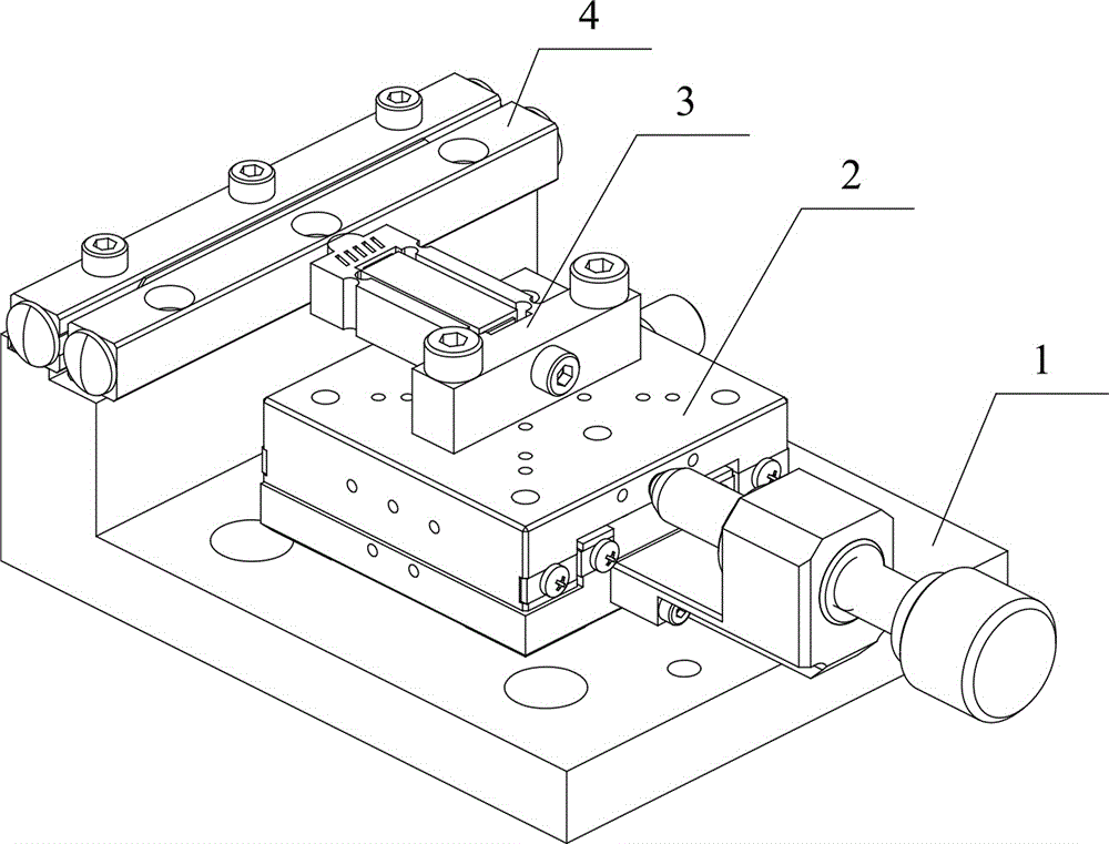
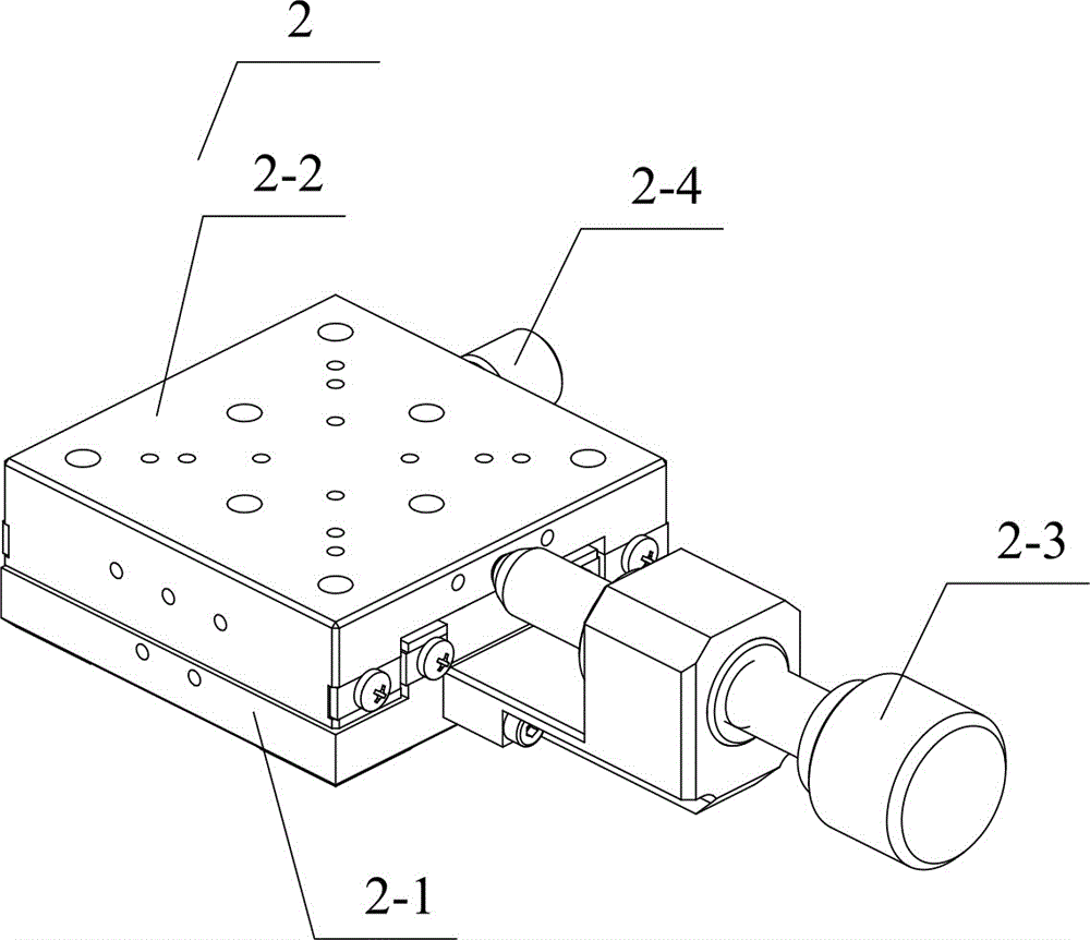
[0024] Specific implementation mode one: combine Figure 1~Figure 9 This embodiment will be described. This embodiment provides a specific implementation of a chute-type precision piezoelectric stick-slip linear motor. The chute-type precision piezoelectric stick-slip linear motor consists of a base 1 , a pre-pressure adjustment mechanism 2 , a chute-type stator 3 and a mover 4 .
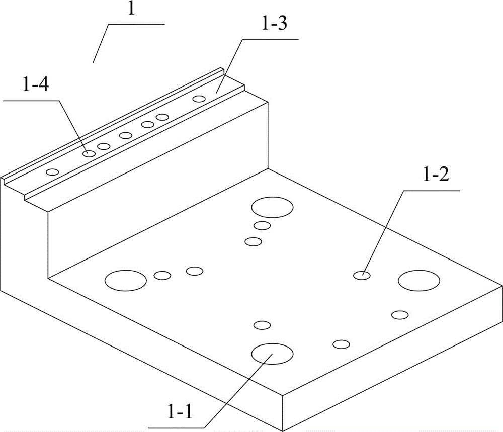
[0025] The base 1 includes a base mounting hole 1-1, a pre-pressure adjustment mechanism mounting hole 1-2, a guide rail fixed installation contact plane 1-3 and a guide rail threaded mounting hole 1-4, and the base 1 can be made of aluminum alloy. The base installation hole 1-1 is a countersunk hole, which can fix the base 1 and other peripheral devices. The pre-pressure adjustment mechanism installation hole 1-2 is used for fixing the pre-pressure adjustment mechanism 2. The guide rail is fixed and installed in contact with The plane 1-3 and the threaded mounting holes 1-4 of the guide rail are ...
specific Embodiment approach 2
[0029] Specific implementation mode two: combination Figure 10 The figures illustrate the present embodiment. This embodiment provides a specific implementation of a method for driving a chute-type precision piezoelectric stick-slip linear motor. The driving method of the chute-type precision piezoelectric stick-slip linear motor is as follows.
[0030] The composite excitation electric signal used in the driving method is compositely superimposed on the sawtooth driving wave in the rapid deformation stage of the stator by the friction regulation wave, the driving wave is a sawtooth wave, and the friction regulation wave is a sine wave. Specifically, the driving method can reduce the frictional resistance between the stator and the mover in the rapid deformation stage, suppress the generation of retreat motion, and optimize the output performance. The period of sawtooth driving wave is T 1 , the excitation voltage amplitude is V 1 , the symmetry is D, and the period of th...
PUM
 Abstract
Description
Claims
Application Information