
Substrate processing apparatus and substrate processing method

a substrate processing and processing apparatus technology, applied in the direction of electrical equipment, semiconductor/solid-state device manufacturing, basic electric elements, etc., can solve the problems of increasing achieve the effect of reducing the cost of the apparatus, reducing the area of the installation of the apparatus, and reliability of the substrate treatmen

Inactive Publication Date: 2007-09-20
MIYAZAKI MITSURU +3
View PDF6 Cites 0 Cited by
  • Summary
  • Abstract
  • Description
  • Claims
  • Application Information

AI Technical Summary

Benefits of technology

[0010] The present invention has been made in view of the above, and it is an object of the present invention to provide a substrate processing apparatus and a substrate processing method which can reliably perform treatment of a substrate with a plurality of liquids without mixing the liquids and simultaneously can achieve a smaller area for installing the apparatus and a lower cost of the apparatus.
[0014] With this arrangement, the second treatment liquid supply device can be mounted integrally with the covering member to simplify the apparatus.
[0016] With this arrangement, the second treatment liquid is not scattered out of the apparatus and can be reused.

Problems solved by technology

However, in the above conventional pretreatment unit 240, since it is necessary to provide two treatment chambers for a chemical liquid treatment and for a cleaning process, not only does an area for installing the apparatus increase so as to occupy a large space, but also the cost of the apparatus increases because a swinging mechanism for the arm 265 is required.

Method used


Image

  • Substrate processing apparatus and substrate processing method
  • Substrate processing apparatus and substrate processing method
  • Substrate processing apparatus and substrate processing method

Examples


first embodiment

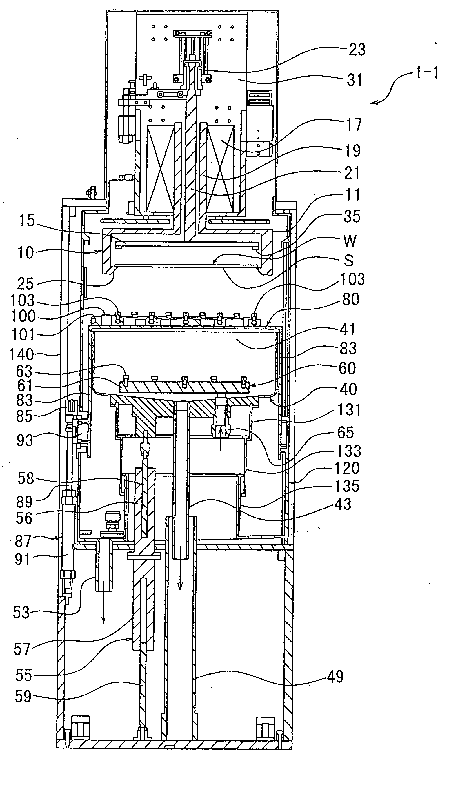
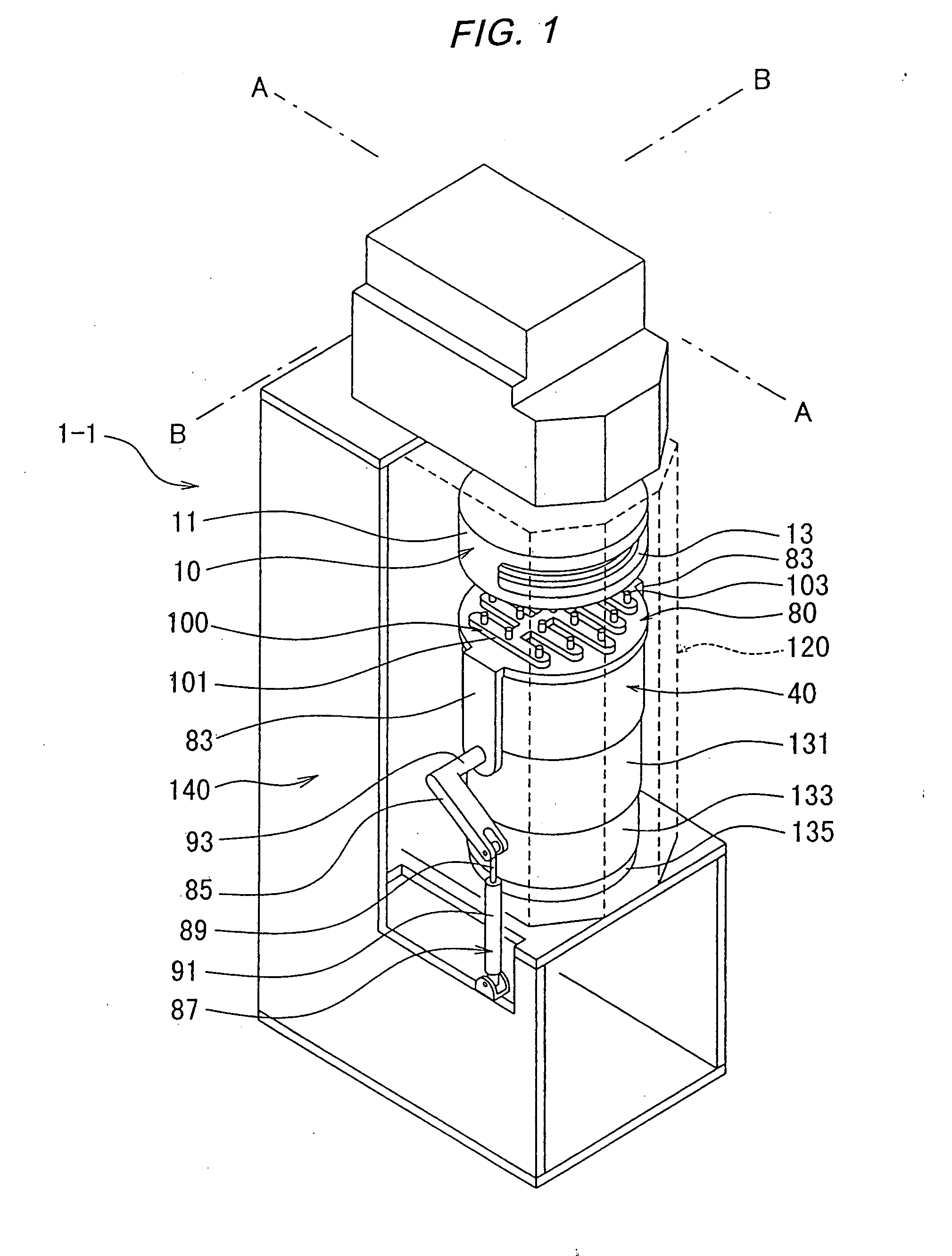
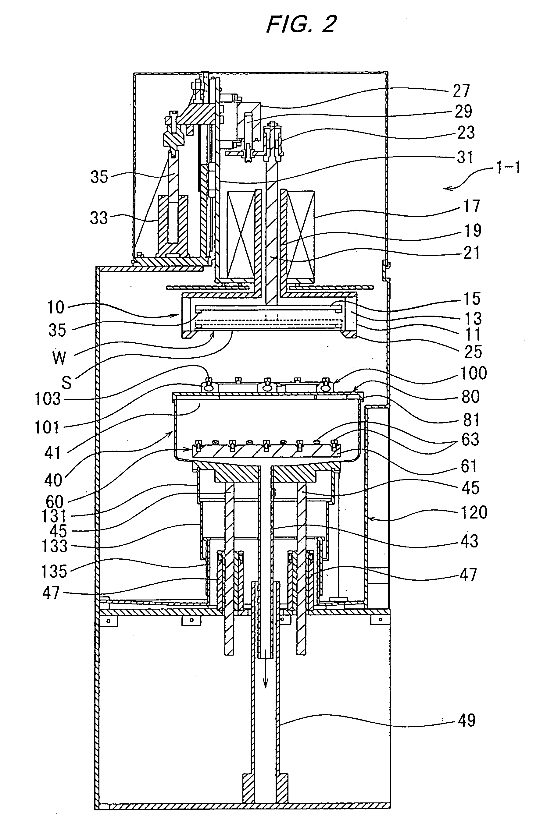
[0058]FIG. 1 is a schematic perspective view showing a substrate processing apparatus 1-1 according to an embodiment in which the present invention is applied to a pretreatment process of an electroless plating, FIG. 2 is a schematic cross-sectional view taken along a line A-A of FIG. 1, and FIG. 3 is a schematic cross-sectional view taken along a line B-B of FIG. 1. As shown in FIGS. 1 through 3, the substrate processing apparatus 1-1 comprises a substrate holding device (substrate holding means) 10 for holding a substrate W, a container 40, a first treatment liquid supply device (first treatment liquid supply means) 60 provided in the container 40, a covering member 80 covering an opening portion 41 of the container 40, a second treatment liquid supply device (second treatment liquid supply means) 100 mounted on an upper surface of the covering member 80, and a second container 120 surrounding the container 40 and holding a second treatment liquid ejected from the second treatment...

second embodiment

[0079]FIG. 8 is a schematic cross-sectional view showing a substrate processing apparatus 1-2 according to an embodiment in which the present invention is applied to an electroless plating apparatus (a cross-sectional view of portions corresponding to FIG. 2). In FIG. 8, the same or corresponding components are designated by the same reference numerals as in the first embodiment. In this embodiment, instead of the base 61 provided in the container 40 and the first treatment liquid supply device 60 having nozzles 63 of the first embodiment, a first treatment liquid supply device (first treatment liquid supply means) 60-2 is constituted by a plating liquid supply pipe 67 extending through one of the rods 45 and connecting to the bottom of the container 40, and a plating liquid discharge pipe 68 extending through the other of the rods 45 and connecting to the bottom of the container 40. Specifically, the first treatment liquid supply device 60-2 is arranged as a first treatment liquid ...

third embodiment

[0083]FIG. 9 is a schematic cross-sectional view showing a substrate processing apparatus 1-3 according to an embodiment in which the present invention is applied to an electrolytic plating apparatus (a cross-sectional view of portions corresponding to FIG. 2). In FIG. 9, the same or corresponding components are designated by the same reference numerals as in the first embodiment. In this embodiment, instead of the base 61 provided in the container 40 and the first treatment liquid supply device 60 having nozzles 63 of the first embodiment, a first treatment liquid supply device (first treatment liquid supply means) 60-3 is constituted by a plating liquid supply / discharge pipe 71 extending through one of the rods 45 and connecting to the bottom of the container 40 for supplying the plating liquid to and discharging the plating liquid from the container 40. The first treatment liquid supply device 60-3 is arranged as a first treatment liquid holding means for storing the first treatm...


PUM

PropertyMeasurementUnit
temperatureaaaaaaaaaa
cut widthaaaaaaaaaa

Abstract

The present invention relates to a substrate processing apparatus and a substrate processing method suitable for processing a substrate with a plurality of liquids. A substrate processing apparatus comprises a substrate holding device for holding a substrate, a container having an opening portion disposed so that the opening portion is opposed to a surface, to be processed, of the substrate, a driving device for moving the container or the substrate holding device between a position at which the container approaches the substrate or a position at which the substrate enters the container, and a position at which the container is positioned away from the substrate, a first treatment liquid supply device for bringing the surface, to be processed, of the substrate which has approached or entered the container into a first treatment liquid, a covering member for covering the opening portion of the container at the position at which the container is positioned away from the substrate, and a second treatment liquid supply device for bringing the surface, to be processed, of the substrate into a second treatment liquid in a state in which the opening portion of the container is covered with the covering member.

Description

BACKGROUND OF THE INVENTION [0001] 1. Field of the Invention [0002] The present invention relates to a substrate processing apparatus and a substrate processing method suitable for processing a substrate with a plurality of liquids. [0003] 2. Description of the Related Art [0004] As an interconnection forming process of a semiconductor device, there has been used a process of embedding a metal (conductive material) in interconnection grooves and contact holes (so-called damascene process). This process comprises embedding a metal such as aluminum, or, recently, copper or silver, in interconnection grooves and contact holes, which have been formed in an interlayer insulating film, and then removing and planarizing excessive metal by chemical mechanical polishing (CMP). [0005] In cases of these types of interconnections, for example, copper interconnections using copper as an interconnection material, surfaces of the interconnections made of copper are exposed to the outside after the...

Claims


Application Information

Patent Timeline
Patent Type & Authority Applications(United States)
IPC IPC(8): H01L21/00
CPCH01L21/67051H01L21/67109Y10T29/41H01L21/6723H01L21/67173
Inventor MIYAZAKI, MITSURUKATSUOKA, SEIJIWATANABE, TERUYUKIMOTOJIMA, YASUYUKI
Owner MIYAZAKI MITSURU
Learn More