An evaporator and a method for vaporizing a substance in an evaporator

a technology of evaporator and substance, which is applied in the direction of indirect heat exchangers, lighting and heating apparatus, and separation processes, etc., can solve the problems of affecting the heat exchange efficiency of the flooded evaporator, the heat exchange properties of the plate heat exchanger and the heat exchange and the difficulty of managing conditions, so as to improve the efficiency of the evaporator and reduce the liquid volume of the evaporator. , the effect o

Active Publication Date: 2019-09-19
VAHTERUS OY
View PDF0 Cites 1 Cited by
  • Summary
  • Abstract
  • Description
  • Claims
  • Application Information

AI Technical Summary

Benefits of technology

[0038]The components used in the evaporator according to the invention can be standard parts or otherwise commonly used, thus the manufacturing costs of the apparatus according to the invention can also be kept low.
[0039]An evaporator according to the invention comprises flow guides or plates arranged tightly on both sides of the plate pack, between the plate pack and the inner surface of the cylindrical shell. The flow guides or plates comprise a first end and a second end in a cross direction of the outer casing, the first ends of the flow guides are attached tightly to the plate pack and the second ends of the flow guides are attached tightly to the cylindrical shell. The flow guides or plates have a length, which is same as the length of the horizontal shell, i.e. the flow guides elongate from a first end plate of the outer casing to the second end plate of the outer casing. Thus, there is no by-pass flow of the substance to be vaporized between the plate pack and the flow guide or plate, and between the flow guide or plate and the outer casing. A flow of a substance to be vaporized is guided between the flow guides or plates into the plate pack without any by-pass flow and thus the forced flow through the plate pack also improves efficiency of the evaporator.
[0040]The structure of the flow guides or plates may vary. In some embodiments only a plate is arranged tightly between the inner surface of the outer casing and the plate pack for blocking the by-pass flow between the plate pack and the outer casing. According to an embodiment of the invention, the structure of the flow guides may be a common plate like structure with the seals. In one embodiment of the invention, the flow guides may be a filler unit which are arranged tightly between the plate pack and the outer shell. The filler unit may be manufactured from plastic, such a HDPE, LDPE, expanded polystyrene or a corresponding material, or it may be manufactured from metal, for example steel, such as carbon steel or stainless steel. In one embodiment of the invention the filler unit may be manufactured from several plates attached together. The aim of the filler units is to block the by-pass flow between the plate pack and the outer casing and also to reduce the liquid volume of the evaporator.
[0041]The liquid level of the substance to be vaporized may vary inside the cylindrical shell depending on e.g. the operating conditions. The liquid level of the substance to be vaporized, such as the refrigerant or other liquid to be vaporized, is advantageously adjusted to about the level of the diameter of the cylindrical shell, whereby the surface area of the substance to be vaporized is as large as possible and the production of vapour per surface area is as small as possible. The ascension speed of the vapour is thus also as small as possible, whereby the generated droplets travelling with the vapour more easily fall back down. Thus the droplet separation is made more efficient. In operation, a liquid level of a substance to be vaporized is substantially in a centre line of the cross section of the cylindrical outer casing, the upper part of the plate pack is above the liquid level.

Problems solved by technology

However, the flow conditions may be difficult to manage and it may also affect heat exchange properties of the plate heat exchanger and the efficiency of the evaporator.
Heat exchange efficiency of the flooded evaporators might also be limited when there is large difference of temperature between a heating substance and a substance to be vaporized in the operation conditions, especially when combined with low vaporization temperature of the substance to be vaporized.

Method used


Image

  • An evaporator and a method for vaporizing a substance in an evaporator

Examples


Embodiment Construction

[0055]Same reference signs have been used in the Figures for parts corresponding to each other.

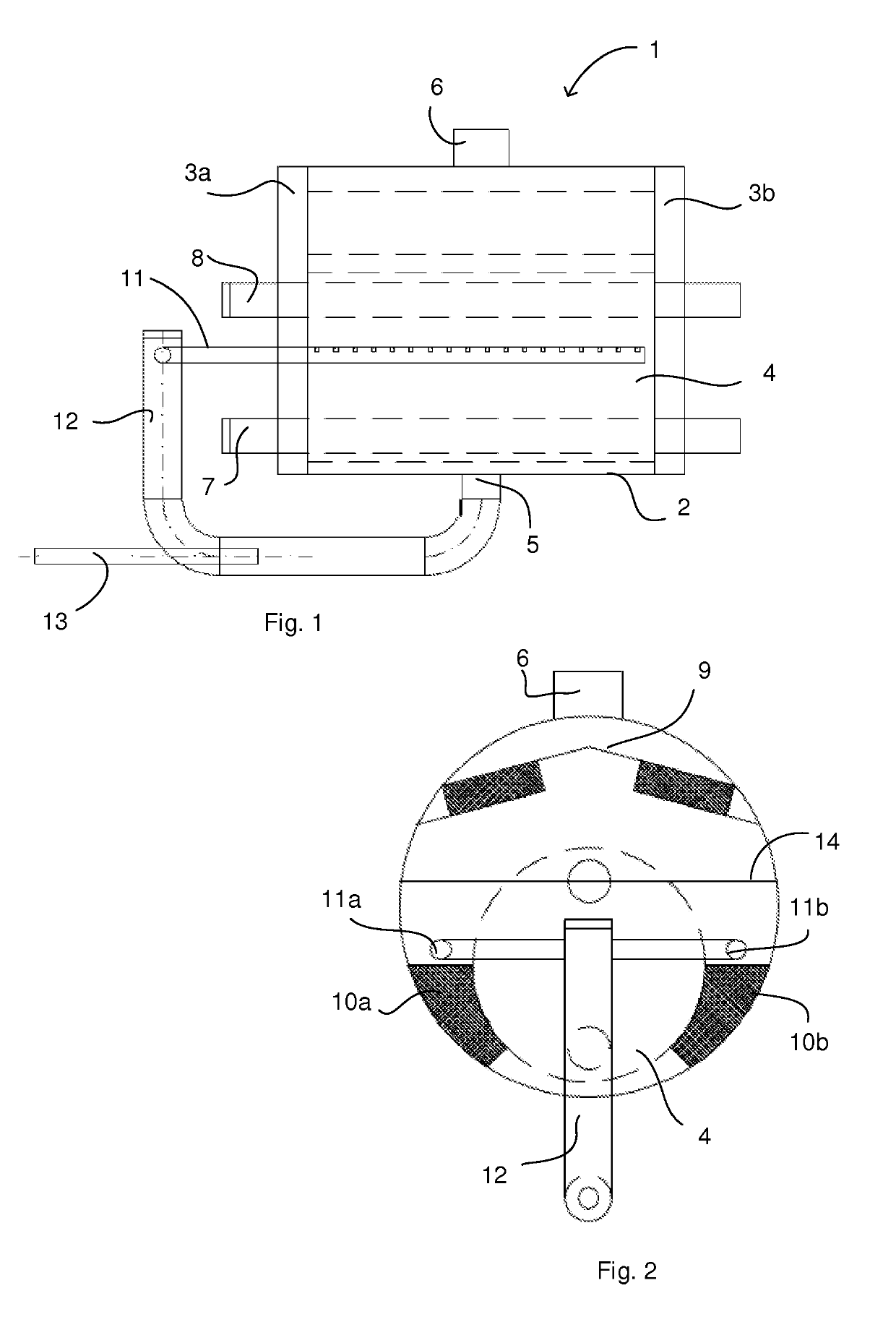
[0056]FIG. 1 shows a longitudinal cross-section of an evaporator 1 according to an embodiment of the invention with a recirculation arrangement.

[0057]The evaporator 1 comprises an outer casing, which is formed of a substantially horizontal cylindrical shell 2 and substantially vertical ends 3a, 3b. A plate pack 4 is arranged inside the cylindrical shell. The plate pack 4 is typically arranged in the lower part of the cylindrical shell and a droplet separator 9 is arranged above the plate pack at the upper part of the cylindrical shell. The plate pack 4 is formed by circular heat exchange plates arranged one on top of each other and the plate pack 4 is arranged inside the horizontal cylindrical shell 2 so that the longitudinal direction of the plate pack is the same as the longitudinal direction of the cylindrical shell. The outer surfaces of the plate pack 4 functions as heat exchange surf...


PUM


Abstract

An evaporator (1) for vaporizing a substance into its gaseous form, which comprises a cylindrical outer shell (2) and a plate pack (4) arranged inside the cylindrical shell in its lower part and a droplet separator (9) arranged above the plate pack. A recirculation of a substance to be vaporized is carried out by using flow guides (10a, 10b) arranged tightly between the plate pack and the outer shell and by an ejector pipe (13) arrangement comprising a collection pipe (11) arranged inside the outer shell.

Description

FIELD OF THE INVENTION[0001]The present invention relates to an evaporator and a method for vaporizing a substance into its gaseous form in an evaporator according to the preambles of the independent claims presented below.BACKGROUND OF THE INVENTION[0002]Evaporators are devices used to turn the liquid form of a substance into its gaseous form.[0003]One kind of evaporators known in the prior art comprise the plate pack functioning as an evaporator and the droplet separator fitted inside the same outer shell. The plate pack is arranged in lower part of the shell and the droplet separator is arranged above the plate pack. The task of the droplet separator is to ensure that refrigerant droplets are not carried to the compressor of the refrigerating machinery. A substance to be vaporized and a generated vapour can flow freely around the plate pack inside the outer shell.[0004]Previously, it is also known evaporator droplet separator systems, where the amount of a substance to be vaporiz...

Claims


Application Information

Patent Timeline
Patent Type & Authority Applications(United States)
IPC IPC(8): B01D1/30B01D1/00
CPCB01D1/305F25B39/02F28D9/0006F28D21/0017F28D2021/0071F28D9/005B01D1/0094F28F9/005F28D9/0043F25B39/022F28D9/00
Inventor SONNINEN, JYRKI
Owner VAHTERUS OY
Why Eureka
Try Eureka