Apparatus and methods for removing a fluid from an article

a technology of apparatus and fluid, applied in the direction of cleaning process and apparatus, chemistry apparatus and processes, thin material processing, etc., can solve the problems of engine disassembly and repair, engine damage, and oxidation damage of brand new or newly refurbished components, so as to achieve low apparatus cost and minimal skilled labor

Inactive Publication Date: 2008-07-24
UNITED TECH CORP
View PDF20 Cites 2 Cited by
  • Summary
  • Abstract
  • Description
  • Claims
  • Application Information

AI Technical Summary

Benefits of technology

[0014]A primary advantage of the present invention is the ability to remove fluids from regions of an apparatus that are difficult to access. The method requires a minimal level of skilled labor and the apparatus cost is low. Once installed, the apparatus passively removes residual fluids over the duration of the storage period. Also, the fluids are able to be collected and disposed of in an environmentally conscious manner.
[0015]These and other objects, features and advantages of the present invention will become apparent in view of the following detailed description and accompanying figures of multiple embodiments, where corresponding identifiers represent like features between the various figures.
[0016]FIG. 1 illustrates an exploded view of a fluid removal and collection apparatus according to an embodiment of the present invention;
[0017]FIG. 2 illustrates a partial cross sectional view of a first embodiment of a guide tube of the apparatus of FIG. 1;
[0018]FIG. 3 illustrates a partial cross sectional view of a second embodiment of a guide tube of the apparatus of FIG. 1;
[0019]FIG. 4 illustrates a partial cross sectional view of a third embodiment of a guide tube of the apparatus of FIG. 1; and

Problems solved by technology

Upon subsequent engine startup, the accumulated preservation fluid can ignite, leading to oxidation damage of brand new or newly refurbished components.
The BOAS segments are particularly susceptible to damage due to their close proximity to the accumulated preservation fluid.
If visual inspection establishes that the BOAS segments or other components are damaged, the engine must be disassembled for repair.
Engine disassembly is both time consuming and can be rather expensive.
Periodic engine starting vaporizes accumulated condensation and purges the fuel system components of harmful corrosion.
This procedure is time consuming, expensive, requires trained personnel and specialized test facilities.
Draining the preservation fluid is not always feasible.
Access ports are not always available in the exact area where preservation fluid accumulates.
Dedicated ports for preservation fluid removal add weight, complexity and manufacturing cost to an engine.
Drain plugs and vacuums may also allow preservation fluid spillage onto the ground, creating environmental remediation concerns.

Method used


Image

  • Apparatus and methods for removing a fluid from an article
  • Apparatus and methods for removing a fluid from an article
  • Apparatus and methods for removing a fluid from an article

Examples


Embodiment Construction

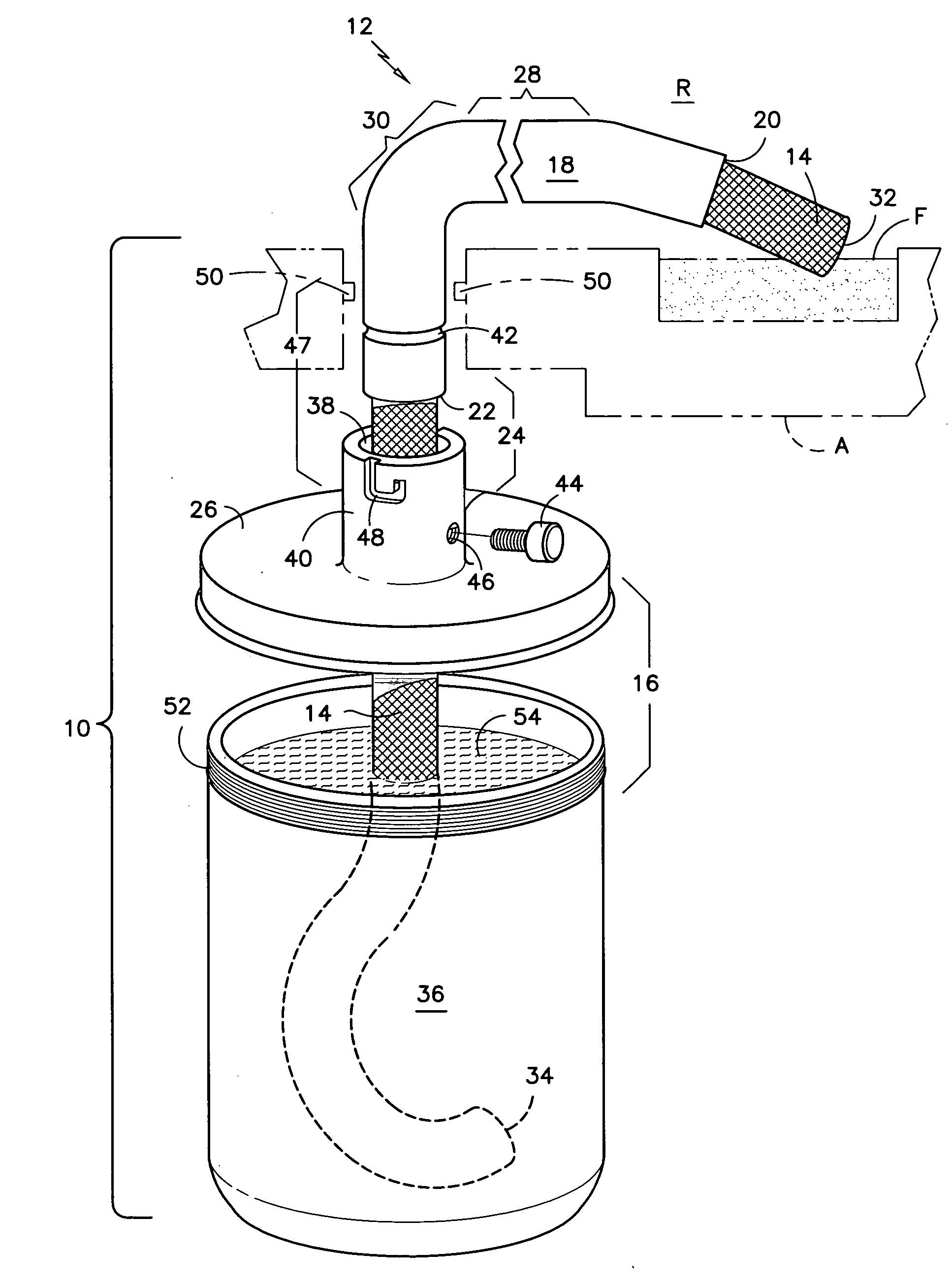
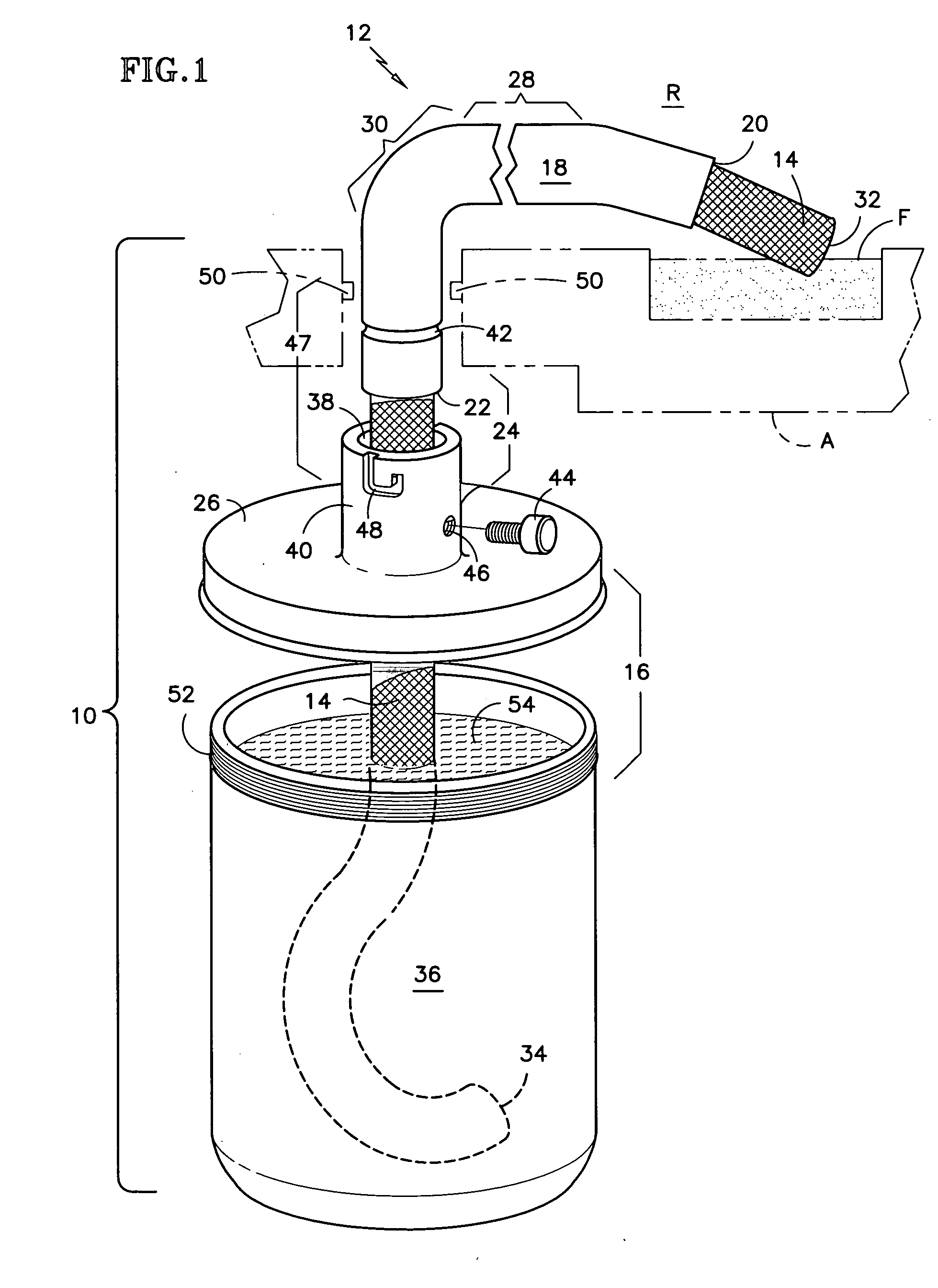
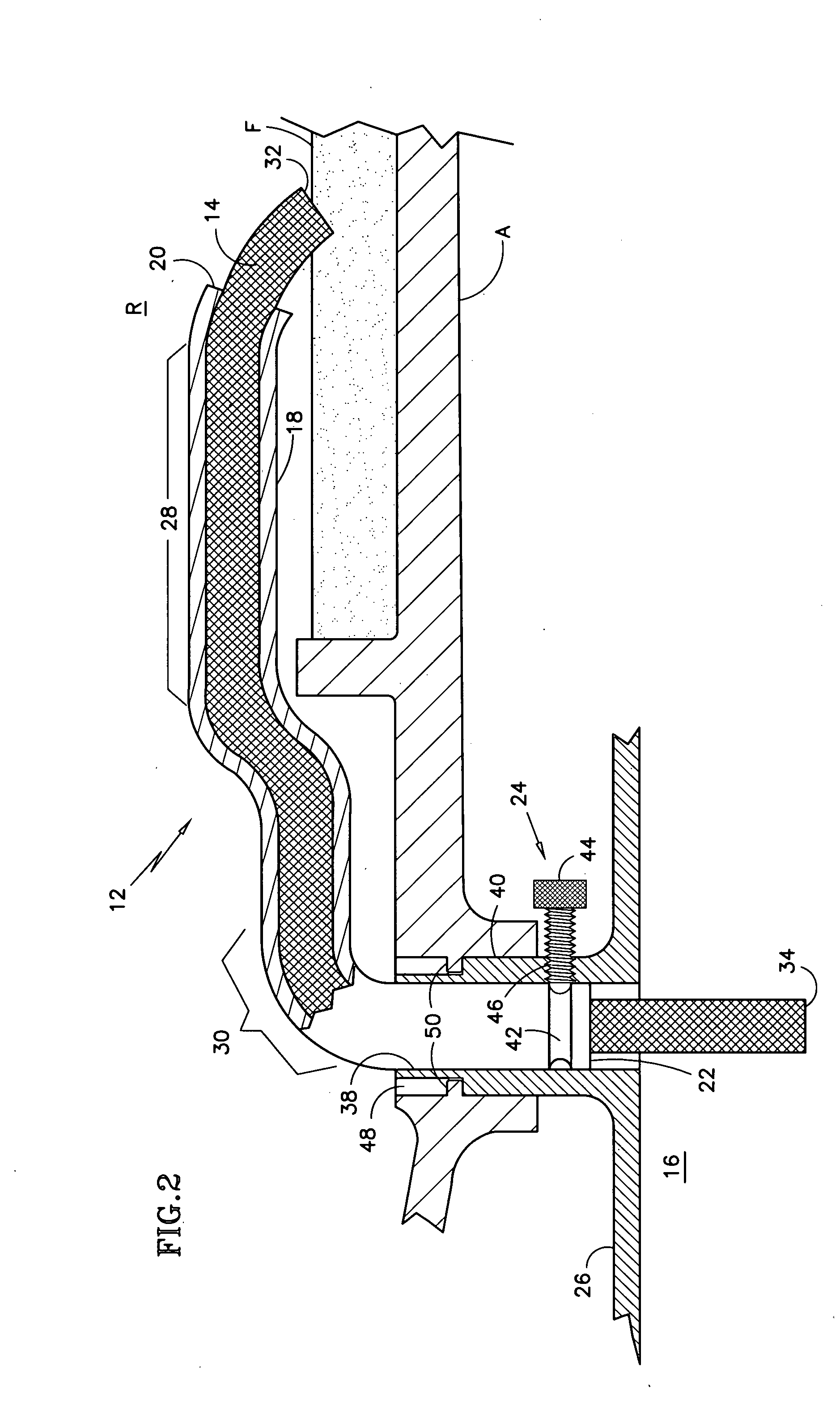
[0021]Referring first to FIG. 1, a fluid removal apparatus 10 broadly comprises a guide tube 12, a wick 14 and a collection vessel 16. The guide tube 12 directs the wick 14 to a fluid F, located in an article A, for transfer to the collection vessel 16. Once removed, the fluid can be disposed of in an environmentally conscious manner. The wick 14 draws the fluid F pool out of the article A by capillary action. Capillary action occurs when the adhesive intermolecular forces between the fluid F and the porous wick 14 are stronger than the cohesive intermolecular forces within the fluid F itself.

[0022]The guide tube 12 is a hollow, thin-walled body, having an internal passageway that is nonporous, unobstructed and as smooth as possible. The guide tube 12 directs the wick 14 around obstructions in the article A to the fluid F. Preferably, the passageway has a cross sectional shape that matches the wick's 14 cross sectional shape, but they may also be shaped differently. Although a circu...


PUM

PropertyMeasurementUnit
flexibleaaaaaaaaaa
corrosionaaaaaaaaaa
rotational speedaaaaaaaaaa

Abstract

Disclosed are exemplary apparatus and methods for removing a fluid from an article. A guide tube is extended into the article so that a tube first end resides in a region proximate the fluid. The guide tube is a rigid, semi-rigid or flexible member, allowing the tube to circumvent obstructions in the article. A wick, made of an absorbent material, is inserted into the tube until a wick first end is proximate the tube first end and is in contact with the fluid. Capillary action draws the fluid into the wick first end, where it is transferred to an opposite, wick second end that is disposed in a collection vessel. The vessel may contain an absorbent material to speed the removal process and simplify the disposal of the fluid. After removal, the fluid may be disposed of in an environmentally conscious manner.

Description

[0001]This invention was made with Government support under F33657-99-D-2051-0013 awarded by the United States Air Force. The Government has certain rights in this invention.BACKGROUND OF THE INVENTION[0002](1) Field of the Invention[0003]The invention relates to components preserved with fluid and more specifically to an apparatus and method for removing accumulated preservation fluid in an environmentally conscious manner.[0004](2) Description of the Related Art[0005]Gas turbine engines typically power aircraft, ships and electrical generators. After original equipment manufacturing (OEM) and subsequent overhaul and repair (O&R) shop visits, an engine is test run to break in mating parts and to ensure the engine meets operational performance limits. Since a lengthy period of time may occur between a test run and actual service use, an engine's internal and external components must be protected from corrosion.[0006]At the end of a typical test run, the engine's rotational speed is ...

Claims


Application Information

Patent Timeline
Patent Type & Authority Applications(United States)
IPC IPC(8): B32B3/10
CPCY10T428/24273B08B9/08
Inventor KWOKA, DAVID
Owner UNITED TECH CORP
Why Eureka
Try Eureka