A clot retrieval system for removing occlusive clot from a blood vessel

a blood vessel and clot technology, applied in the field of clot retrieval system for removing occlusive clots from blood vessels, can solve the problems of serious patient harm, occlusion of blood vessels, and significant limitations of currently available devices, and achieves the effects of facilitating easy entry of large clots, reducing shear forces, and high modulus

Active Publication Date: 2019-06-06
NEURAVI
View PDF0 Cites 15 Cited by
  • Summary
  • Abstract
  • Description
  • Claims
  • Application Information

AI Technical Summary

Benefits of technology

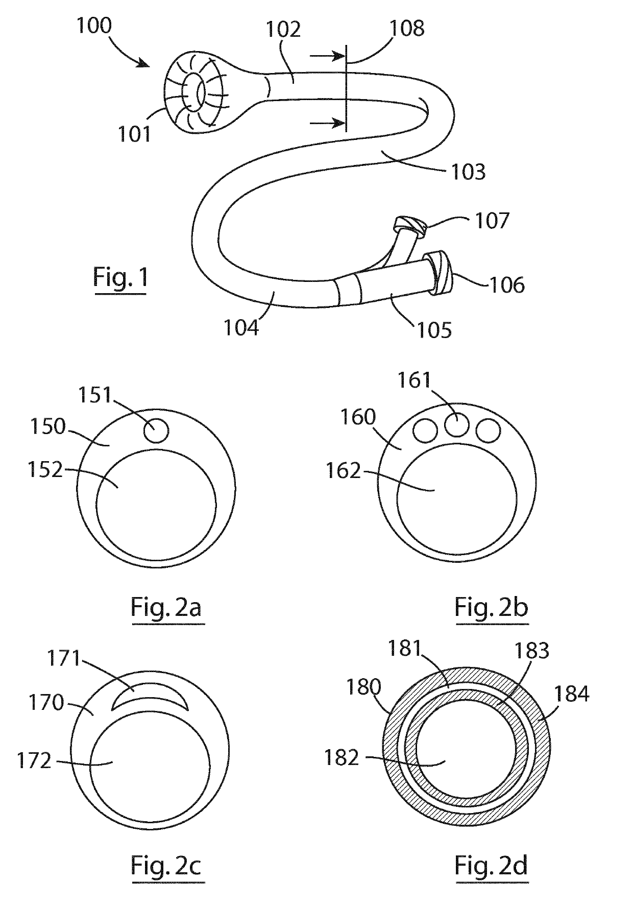
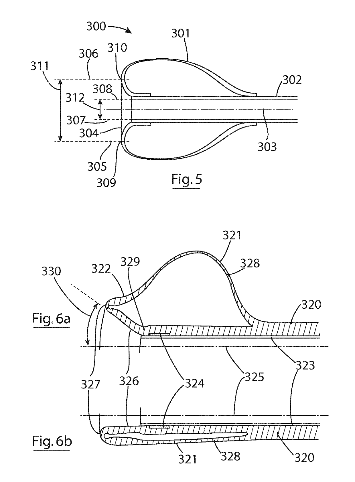
[0015]In one series of embodiments multiple balloons are employed on the catheter shaft. This has the benefit of allowing individual balloon properties to be tailored for specific tasks. For example a low pressure, compliant, balloon may be designed to seal against the vessel wall to help create flow arrest, while another balloon may be designed to adopt a funnel-like shape at the distal catheter tip to minimize shear forces on the clot and facilitate easy entry of large and / or firm clots into the catheter mouth. In some cases a higher pressure, less compliant, balloon may be employed to help keep the catheter tip from lying too close to the vessel wall and impeding clot retrieval.
[0016]The materials used in the construction of this catheter must be carefully selected. For high pressure balloons relatively high modulus materials such as PET or Polyamide make good choices, but for certain inflatable portions of the catheters of this invention a much softer more compliant material is desired. This preferably comprises an amorphous elastomeric polymer, so that it can be stretched / strained under inflation pressure to a diameter at least twice and as much as 5 times its uninflated diameter and recover most or all of its unexpanded shape upon deflation. This requires the material to withstand an elastic strain of at least 200% and ideally 500% or more with minimal levels of plastic deformation. Recoverable strains of such a high level are greatly facilitated by crosslinking of the polymer chains, and hence thermoset materials such as silicone rubbers may be a good choice for a compliant balloon. However silicone is not an easy material to join to a second material as it cannot easily be melted and made miscible with another material to form a strong and low profile weld joint for example. For this reason polyurethane elastomers are a preferred material for the balloon of this invention. In particular thermoplastic polyurethane elastomers would make an ideal material as this can be melted as part of a welding or joining process, or can be solvent bonded or adhesively bonded. In addition such polyurethanes can be joined to compatible families of materials in order to create a greater stiffness gradient along the length of the catheter than would be possible if limited to polyurethanes alone. For example, a very soft polyurethane can be used for the balloon and very distal section of the catheter; one or more Pebax (polyether block amide copolymer) materials may be used for a mid-section of the catheter; and polyamide material(s) may be used for the proximal section of the catheter shaft. This series of materials offers increasingly higher durometers and Young's modulus (or stiffness), so that a very flexible distal shaft region can be smoothly transitioned to a much stiffer proximal shaft region. The Polyether block amide material has the advantage of being joinable to both the Polyurethane and the Polyamide, even though the Polyurethane and the Polyamide are not so easily joined to one another.

Problems solved by technology

However, despite the benefits provided by balloon guides, there are significant limitations to currently available devices:
One of these limitations is due to the location of the balloon on the catheter.
This dead space is a region from which clot cannot easily be aspirated or sucked, and thus if clot fragments become lodged in this region they may escape distally upon deflation of the balloon (which must be done prior to removal of the catheter from the patient), potentially causing occlusion of a blood vessel and serious patient harm.
A second limitation of conventional balloon guide catheters is the level of shear stress induced in the clot as it withdrawn into the catheter.
This abrupt change can create a high shear stress at the interface between clot and catheter tip, which can result in shearing or tearing of the clot, releasing clot fragments which may then hang up in the previously mentioned dead space, or causing large portions or the entirety of the clot to be dislodged from the stent-retriever or aspiration catheter which has retracted it to the balloon guide catheter.
If these clot portions or fragments are not then aspirated fully into the balloon guide catheter they may travel distally and cause injury or death.

Method used


Image

  • A clot retrieval system for removing occlusive clot from a blood vessel
  • A clot retrieval system for removing occlusive clot from a blood vessel
  • A clot retrieval system for removing occlusive clot from a blood vessel

Examples


Embodiment Construction

[0132]Specific embodiments of the present invention are now described in detail with reference to the Figures, wherein identical reference numbers indicate identical or functionality similar elements. The terms “distal” or “proximal” are used in the following description with respect to a position or direction relative to the treating physician. “Distal” or “distally” are a position distant from or in a direction away from the physician. “Proximal” or “proximally” or “proximate” are a position near or in a direction toward the physician.

[0133]Accessing cerebral, coronary and pulmonary vessels involves the use of a number of commercially available products and conventional procedural steps. Access products such as guidewires, diagnostic catheters and microcatheters are described elsewhere and are regularly used in cath lab procedures. It is assumed in the descriptions below that these products and methods are employed in conjunction with the device and methods of this invention and d...


PUM


Abstract

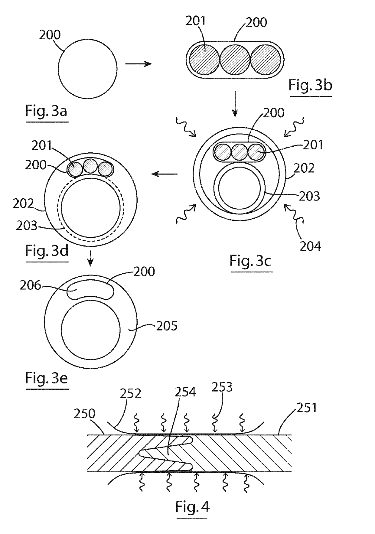
A clot capture catheter comprises an elongate tubular shaft having a proximal end, a distal end and an inflatable expansile member at the distal end. The expansile member is inflatable from a collapsed delivery configuration to an expanded configuration. In the expanded configuration, the expansile member extends to define a funnel shape having an enlarged distal clot entry mouth at the distal-most end of the catheter. In the expanded configuration, the expansile member may extend distally beyond the distalmost tip of the shaft. The expansile member may be integral with the distal tip of the catheter shaft.

Description

FIELD OF THE INVENTION[0001]This invention relates to devices intended for use in procedures involving removing acute blockages from blood vessels. Acute obstructions may include clot, misplaced devices, migrated devices, large emboli and the like. Thromboembolism occurs when part or all of a thrombus breaks away from the blood vessel wall. This clot (now called an embolus) is then carried in the direction of blood flow. An ischemic stroke may result if the clot lodges in the cerebral vasculature. A pulmonary embolism may result if the clot originates in the venous system or in the right side of the heart and lodges in a pulmonary artery or branch thereof. Clots may also develop and block vessels locally without being released in the form of an embolus—this mechanism is common in the formation of coronary blockages. The invention is particularly suited for use in cases involving the removal of clot from cerebral arteries in patients suffering acute ischemic stroke (AIS), from corona...

Claims


Application Information

Patent Timeline
Patent Type & Authority Applications(United States)
IPC IPC(8): A61B17/22A61M25/10A61F2/95
CPCA61B17/22032A61M25/1002A61M25/1011A61F2/95A61M2205/0216A61B2017/22079A61M2025/1084A61M2025/1079A61M2025/1013A61M2025/109A61F2002/9528A61B2017/22062A61B2017/22054A61M2025/1065A61B17/22A61M25/104A61B2017/22001A61B2017/22065A61B2017/22081A61B2017/22038A61B17/221A61B2017/22067A61B2017/22069A61B2217/005A61M25/005A61M25/0032A61M2025/1059A61L29/04A61M25/1018A61M25/1034A61B2017/2215A61M2025/1093A61M2025/1047A61M2025/0042
Inventor VALE, DAVIDCASEY, BRENDANFAHY, BRIANMCARDLE, KEVINBRADY, EAMONAMSTUTZ, JILLHOLIAN, MAEVEKING, DANIELGILVARRY, MICHAEL
Owner NEURAVI
Why Eureka
Try Eureka