Fluid energy transfer device with improved bearing assemblies

a technology of energy transfer device and bearing assembly, which is applied in the direction of liquid fuel engine, combination engine, machine/engine, etc., can solve the problems of high cost, high cost, and high cost, and achieve the effect of minimizing by-pass leakage, and minimizing operating fluid shear for

Active Publication Date: 2015-06-30
YARR GEORGE A
View PDF61 Cites 4 Cited by
  • Summary
  • Abstract
  • Description
  • Claims
  • Application Information

AI Technical Summary

Benefits of technology

[0026]The feature of precisely setting the rotational axis or axial position of a particular rotor with a bearing assembly has the advantage of maintaining a fixed-gap clearance of the associated rotor with at least one surface of the housing or the other rotor. Depending on its location, the fixed-gap clearance between the rotor surface and housing surface or the other rotor surface is set at a distance that is 1) greater than the boundary layer of the operating fluid used in the device in order to minimize operating fluid shear forces or 2) at a distance that is optimal for a) minimizing by-pass leakage i) between chambers formed by the engagement of the female and male gear profiles, ii) between these chambers and the inlet and outlet passages, and iii) between the inlet and outlet passages and also b) for minimizing operating fluid shear forces. In one preferred embodiment, both rotors have hubs that are mounted with bearing assemblies in the housing in order to control all interface surfaces between each rotor and its opposing housing surface or between the interface surfaces of two opposing rotor surfaces. This has the advantage of keeping frictional loses in the device to a minimum and allowing the device to function as a very efficient expansion engine or fluid compressor.
[0027]In a configuration that features a rolling element bearing assembly to fix the axial position or rotational axis or both of the outer rotor, the inner rotor has a bored central portion that allows for rotation about a hub that extends from the end plate. Fixing of the rotational axis of the outer rotor with a bearing assembly has the advantage of eliminating the need to provide pressure equalizing grooves between the chambers to prevent unbalanced radial hydraulic forces that result in contact of the outer radial surface of the outer rotor with the cylindrical housing and attendant frictional loss and even seizing of the rotor and housing. Another feature of this embodiment is the use of a rolling element bearing positioned between the end plate hub and the inner surface of the central bore portion of the inner rotor which has the advantage of reducing substantially the frictional losses from the rotation of the inner rotor about the end plate hub. This configuration also features the use of a bearing assembly, e.g., a thrust bearing such as a needle thrust bearing, to maintain a minimum fixed-gap clearance between the inner face of the end plate and the end face of the inner rotor. This has the further advantage of eliminating contact between the inner rotor end face and the end plate and setting the minimum fixed-gap clearance that is maintained between the two surfaces. At operating pressures, hydraulic forces urge the inner rotor to the minimum fixed-gap clearance position thereby also maintaining a fixed-gap clearance between the opposite face of the inner rotor and the inner face of the closed end of the outer rotor.
[0028]The present invention maintains superior chamber to chamber sealing ability over long periods of use. In prior art devices, gear lobe crown wear occurs as a result of the need to use a small gear profile clearance between the inner and outer rotor gear profiles, e.g., 0.0002 inch, in order to maintain chamber to chamber sealing ability while the required clearance between the outer rotor and housing needs to be several times larger, e.g., 0.005-0.008 inch, in order to form a hydrodynamic journal bearing. During running, small eccentricities of the outer rotor axis cause contact of the lobe crowns of the inner and outer rotors resulting in lobe wear and degradation of the chamber to chamber sealing ability. The feature of using rolling element bearings to set and maintain the axes of both rotors to within a few ten-thousandths of an inch and even less when pre-loaded are used has the advantage of eliminating shear on the lobe crowns and maintaining superior chamber to chamber sealing ability over the life of the device.
[0029]The present invention is especially useful in handling two-phase fluids in expansion engines and contracting fluid devices (compressors). When operating as an engine, the device features and output shaft that has the advantage of accommodating an integrated condensate pump with the further advantages of eliminating pump shaft seals and attendant seal fluid losses and matching pump and engine capacity in Rankine cycles where the fluid mass flow rate is the same through both the engine and condensate pump.
[0030]The invention also features a vent conduit from the housing cavity to a lower pressure input or output port which has the advantage of controlling built-up fluid pressure in the internal housing cavity thereby reducing fluid shear forces and also of alleviating strain on the housing structure especially when used as a hermetically sealed unit with magnetic drive coupling. The invention also features a pressure regulating valve, such as a throttle valve (automatic or manual), to control operating fluid pressure in the housing cavity. By controlling and maintaining a positive pressure in the housing cavity, bypass leakage at the interface between the outer rotor and the end plate and excessive pressure build up with attendant large fluid shear force energy losses and housing structural strain are substantially reduced.

Problems solved by technology

One significant problem with such devices are efficiency losses and part wear due to friction between the various moving parts of the configuration.
Such loss of efficiency can be especially severe when the device is used as an engine or motor rather than a pump.
However, such bearings have been used mainly to control frictional losses between the drive shaft and the device housing rather than the internal mechanism of the device itself.
Minto recognizes that binding between the outer radial surface of the rotating outer gear and the close-fitting cylindrical enclosure due to differences in pressure between the inner and outer faces of the outer rotor element is a problem.
However, Dominique also realizes that one of the problems with this type of device is by-pass leakage between the inlet and outlet ports of the device.
Unfortunately this can lead to contact of the rotors with the end plate and attendance high frictional losses and loss of efficiency.
Although such losses are not a major design factor when the device is used as a pump, it is of major concern when using the device as an engine and a motor.
Here such frictional losses can be a major detriment to the efficiency of the engine.
In addition to frictional losses, the basic design of the device causes wear of the gear profiles, especially at the gear lobe crowns resulting in a degradation in chamber to chamber sealing ability.
During running, small eccentricities of the outer rotor axis cause contact of the crowns of the inner and outer rotor lobes as they pass by each other resulting in wear of the gear lobe crowns and degradation of the chamber to chamber sealing ability.

Method used


Image

  • Fluid energy transfer device with improved bearing assemblies
  • Fluid energy transfer device with improved bearing assemblies
  • Fluid energy transfer device with improved bearing assemblies

Examples


Embodiment Construction

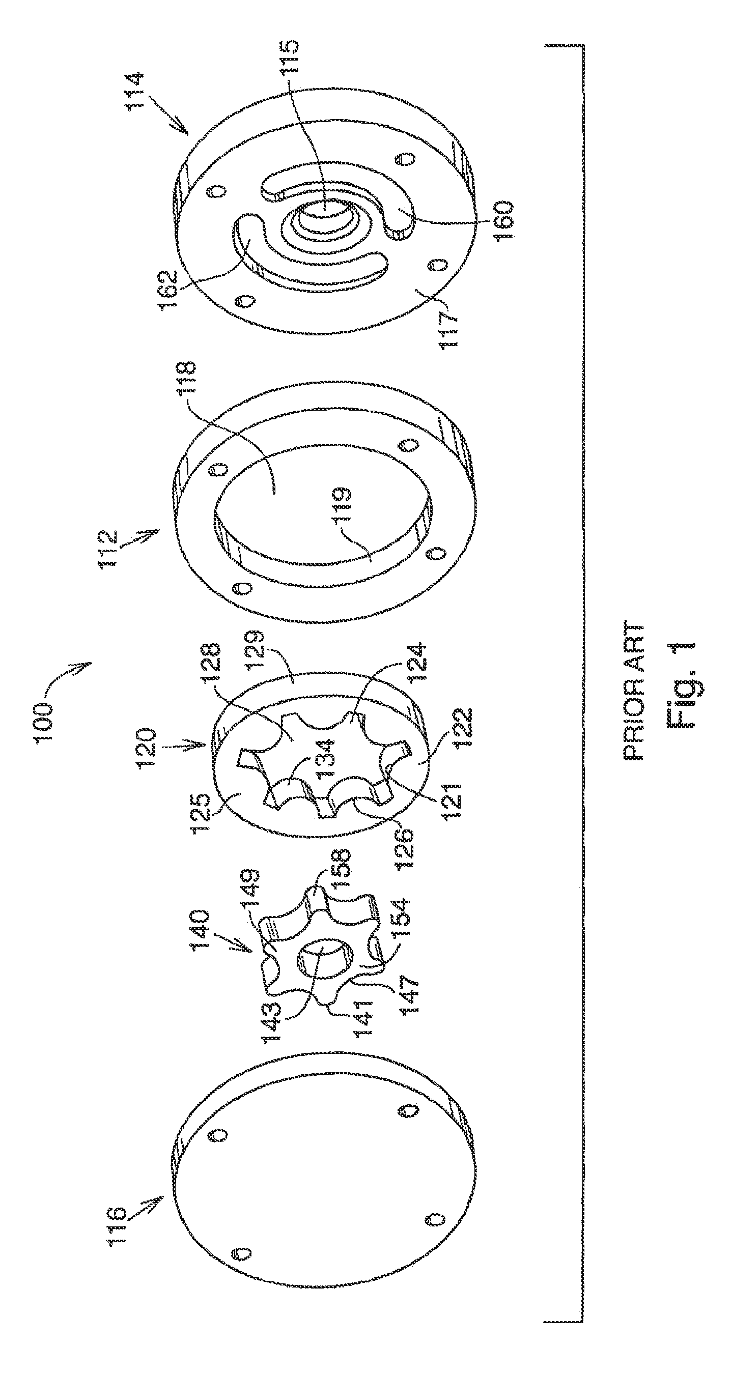
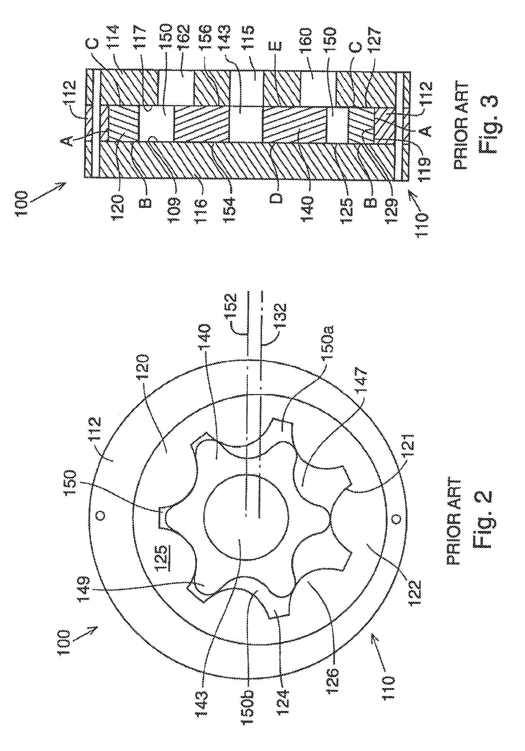
[0053]With reference to the drawings and initially FIGS. 1-3, a conventional trochoidal element, fluid displacement device (pump or engine) of which a species is a gerotor is generally denoted as device 100 and includes a housing 110 with a cylindrical portion 112 having a large axial cylindrical bore 118 typically closed at opposite ends in any suitable manner, such as by removable static end plates 114 and 116 to form a housing cavity substantially identical with cylindrical housing bore 118.

[0054]An outer rotor 120 freely and rotatably mates with the housing cavity (axial bore 118). That is, the outer peripheral surface 129 and opposite end faces (surfaces) 125 and 127 of outer rotor 120 are in substantially fluid-tight engagement with the inner end faces (surfaces) 109, 117 and peripheral radial inner surface 119 which define the housing cavity. The outer rotor element 120 is of known construction and includes a radial portion 122 with an axial bore 128 provided with a female ge...


PUM


Abstract

A trochoidal gear pump or engine uses a coaxial hub with an outer and / or inner rotor and an associated rolling element bearing assembly that uses pre-loaded bearings to precisely set the rotational axis and / or the axial position of the rotor with which it is associated. This allows the fixed-gap clearance between the rotor surfaces and the housing or other rotor surfaces to be set at a distance that minimizes operating fluid shear forces and / or by-pass leakage and eliminates gear tooth wear thus preserving effective chamber to chamber sealing. The device is useful in handling gaseous and two-phase fluids in expansion / contracting fluid engines / compressors and can incorporate an output shaft for an integrated condensate pump for use with Rankine cycles. A vent from the housing cavity to a lower pressure input or output port regulates built-up fluid pressure in the housing, thereby optimizing the efficiency of the device by controlling bypass leakage.

Description

CROSS-REFERENCE TO RELATED APPLICATIONS[0001]The subject matter of this application relates to U.S. Pat. No. 6,174,151, the entire disclosure of which is hereby incorporated herein by reference in its entirety. This application is a national stage entry of International Patent Application No. PCT / US2011 / 035383, filed May 5, 2011, which claims priority to and the benefit of U.S. Provisional Patent Application Ser. No. 61 / 331,572, filed on May 5, 2010, the disclosures of which are hereby incorporated herein by reference in their entiretyFIELD OF THE INVENTION[0002]The present invention relates to energy transfer devices that operate on the principal of intermeshing trochoidal gear fluid displacement and more particularly to the reduction of frictional forces in such systems.BACKGROUND OF THE INVENTION[0003]Trochoidal gear, fluid displacement pumps and engines are well-known in the art. In general, a lobate, eccentrically-mounted, inner male rotor interacts with a mating lobate female ...

Claims


Application Information

Patent Timeline
Patent Type & Authority Patents(United States)
IPC IPC(8): F01C1/10F01C11/00F01C21/02F04C2/14
CPCF01C1/103F01C11/002F01C21/02F04C2/14F04C2210/24F04C2240/54
Inventor YARR, GEORGE A.
Owner YARR GEORGE A
Why Eureka
Try Eureka