
Method of and system for performing detection on or characterization of a sample

a detection method and sample technology, applied in the direction of instruments, measurement devices, and analysis of solids using sonic/ultrasonic/infrasonic waves, can solve the problems of reducing damage, reducing damage, and reducing the damage issue, so as to achieve time-efficient and accurate results

Active Publication Date: 2019-12-19
NEDERLANDSE ORG VOOR TOEGEPAST-NATUURWETENSCHAPPELIJK ONDERZOEK (TNO)
View PDF2 Cites 2 Cited by
  • Summary
  • Abstract
  • Description
  • Claims
  • Application Information

AI Technical Summary

Benefits of technology

This patent describes a new method for mapping the surface and subsurface characteristics of a sample using atomic force microscopy. The method is efficient and accurate, and can provide stiffness and viscoelasticity maps of the sample. It minimizes damage to the surface and can be performed at high throughput. The deformation forces on the sample are minimized, resulting in a reduction of shear forces. The method can also provide a three-dimensional stiffness or visco elasticity of the sample.

Problems solved by technology

Since the subsurface AFM is operated in the contact mode, it has the disadvantages that it can damage the sample, especially since higher force application is needed to get high signal to noise ratios.
Higher set point force will result in higher shear forces which are known to damage the sample and may cause drift during the measurement in the subsurface signal.
Intermittent contact resonance has shown however to reduce the damage issue, but not fully.
However, forces are not well specified in this mode and quantitative (subsurface) imaging is therefore difficult.
Moreover, it does not solve the problem of coupling surface and subsurface information.

Method used


Image

  • Method of and system for performing detection on or characterization of a sample
  • Method of and system for performing detection on or characterization of a sample
  • Method of and system for performing detection on or characterization of a sample

Examples


Embodiment Construction

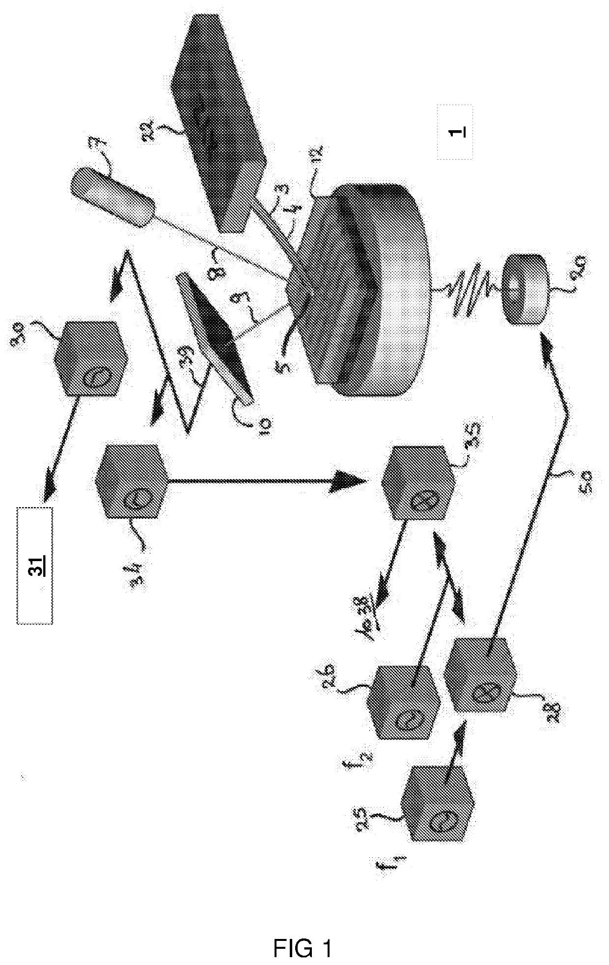
[0027]FIG. 1 schematically illustrates an atomic force microscopy system (AFM) 1, suitable for use in a method of the present invention and in accordance with an embodiment of the present invention. The system 1 comprises a probe 3 having a cantilever 4 and a probe tip 5. The probe tip 5 is brought in contact with a surface of a sample 12. A light source 7, typically a laser, provides an optical signal beam 8 that is incident on the back of the probe tip 5. A reflected optical beam 9 is received by an optical sensor 10. Any vibration of the probe tip 5 perpendicular to the surface sample 12 will result in a deflection of the reflected optical beam 9. This deflection can be accurately determined by means of optical sensor 10 which provides an (electrical) output signal 39 for further analysis.

[0028]The detection method of the present invention applies, in addition to performing surface topography measurements, an acoustic vibration signal to the sample 12, which results in acoustic v...


PUM

PropertyMeasurementUnit
frequency amplitudeaaaaaaaaaa
cutoff frequencyaaaaaaaaaa
heightaaaaaaaaaa

Abstract

The present document relates to a anatomic force microscope comprising a probe comprising a probe tip configured to sense a sample disposed proximate to the probe tip, a detector to detect a deflection of the probe tip, an actuator coupled to the probe and configured to move the probe in a sense state with the sample at a predetermined force set point and a vibrator in communication with the sample to provide a vibration to the sample, the vibration comprising a modulation frequency, wherein the acoustic vibrator is configured to provide the vibration in a modulation period after an initial sense period without modulation and wherein the probe is moved during or after said modulation period to a successive sample position over said sample while moving the probe in a non-contact state.

Description

FIELD OF THE INVENTION[0001]The present invention is directed at a method for mapping surface and subsurface characteristics of a sample. The invention is further directed at a method for performing atomic force microscopy, and at an atomic force microscopy system.BACKGROUND[0002]In recent advances of atomic force microscopy so called subsurface probe microscopy (also known as subsurface AFM) has shown unique capabilities to measure nanostructures buried below the surface. Subsurface AFM is typically operated in contact-mode feedback wherein a topography image is obtained using contact-mode feedback of the low-frequency (<2 kHz) portion of the cantilever deflection signal, while simultaneously recording a subsurface image from the high frequency amplitude and phase at modulation frequency.[0003]The schematic of the working principle of this prior art method is shown in FIG. 1.[0004]Since the subsurface AFM is operated in the contact mode, it has the disadvantages that it can dama...

Claims


Application Information

Patent Timeline
Patent Type & Authority Applications(United States)
IPC IPC(8): G01N29/06G01N29/24G01Q60/38G01N29/265G01N21/17
CPCG01N29/2418G01N29/0681G01N29/265G01N21/1702G01Q60/38G01Q60/32G01N29/041G01N2291/263
Inventor SADEGHIAN MARNANI, HAMEDKRAMER, LUKASVAN ES, MAARTEN HUBERTUS
Owner NEDERLANDSE ORG VOOR TOEGEPAST-NATUURWETENSCHAPPELIJK ONDERZOEK (TNO)
Learn More