Reluctor ring installation tool

a technology for installing tools and reluctor rings, which is applied in the direction of manufacturing tools, valve arrangements, machines/engines, etc., can solve the problems of prone to error, damage to reluctor rings, and often damaged reluctor rings upon their own, so as to improve accuracy, improve time efficiency, and reduce errors

Active Publication Date: 2010-05-18
GOODSON MFG
View PDF10 Cites 0 Cited by
  • Summary
  • Abstract
  • Description
  • Claims
  • Application Information

AI Technical Summary

Benefits of technology

[0023]In at least one embodiment of the subject invention, it is an object to simplify and / or make more efficient the installation of a reluctor ring on a crankshaft. In another embodiment, it is an object of the invention to provide a device that simplifies the rotational alignment and installation of a reluctor ring on a crankshaft through the use of at least two alignment mechanisms (e.g. pins or dowels) in cooperation with a tool body.
[0025]In still additional embodiments, it is an object to provide a method of installing a reluctor ring, employing an installation tool, which is more time efficient, accurate, and less prone to error.

Problems solved by technology

For example, when repairing or reconditioning a crankshaft, the reluctor ring is often damaged upon its removal.
Damage to a reluctor ring can occur in other circumstances as well and / or it may become necessary to periodically clean debris from between the reluctor ring and crankshaft.
Circumstances in which reluctor rings are damaged are not uncommon since the reluctor ring is traditionally a relatively weak structure that is highly susceptible to warping or breakage e.g. such as during removal.
A difficulty encountered in the reassembly of the crankshaft and reluctor ring is the alignment of the reluctor ring with respect to the crankshaft.

Method used


Image

  • Reluctor ring installation tool
  • Reluctor ring installation tool
  • Reluctor ring installation tool

Examples


example

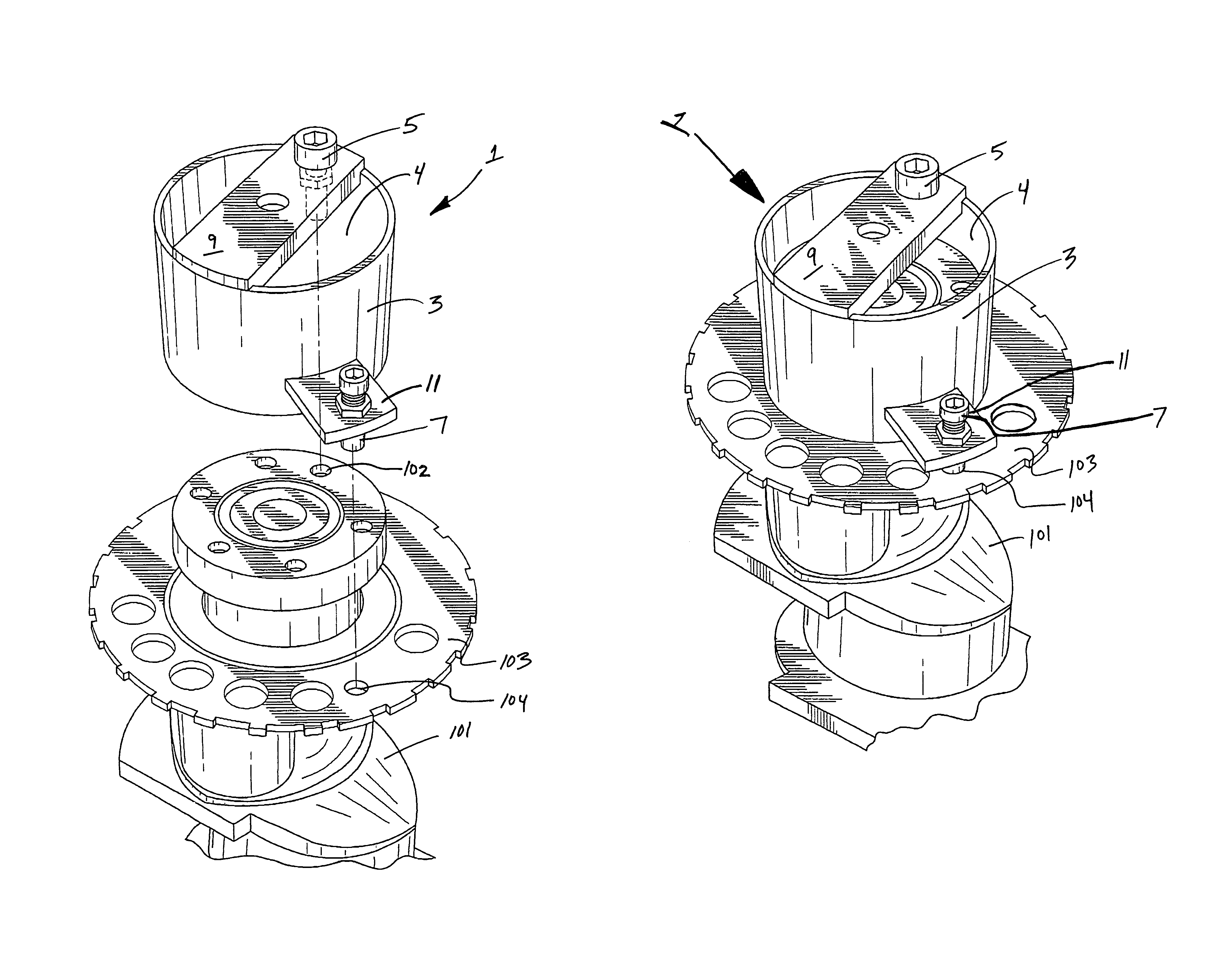
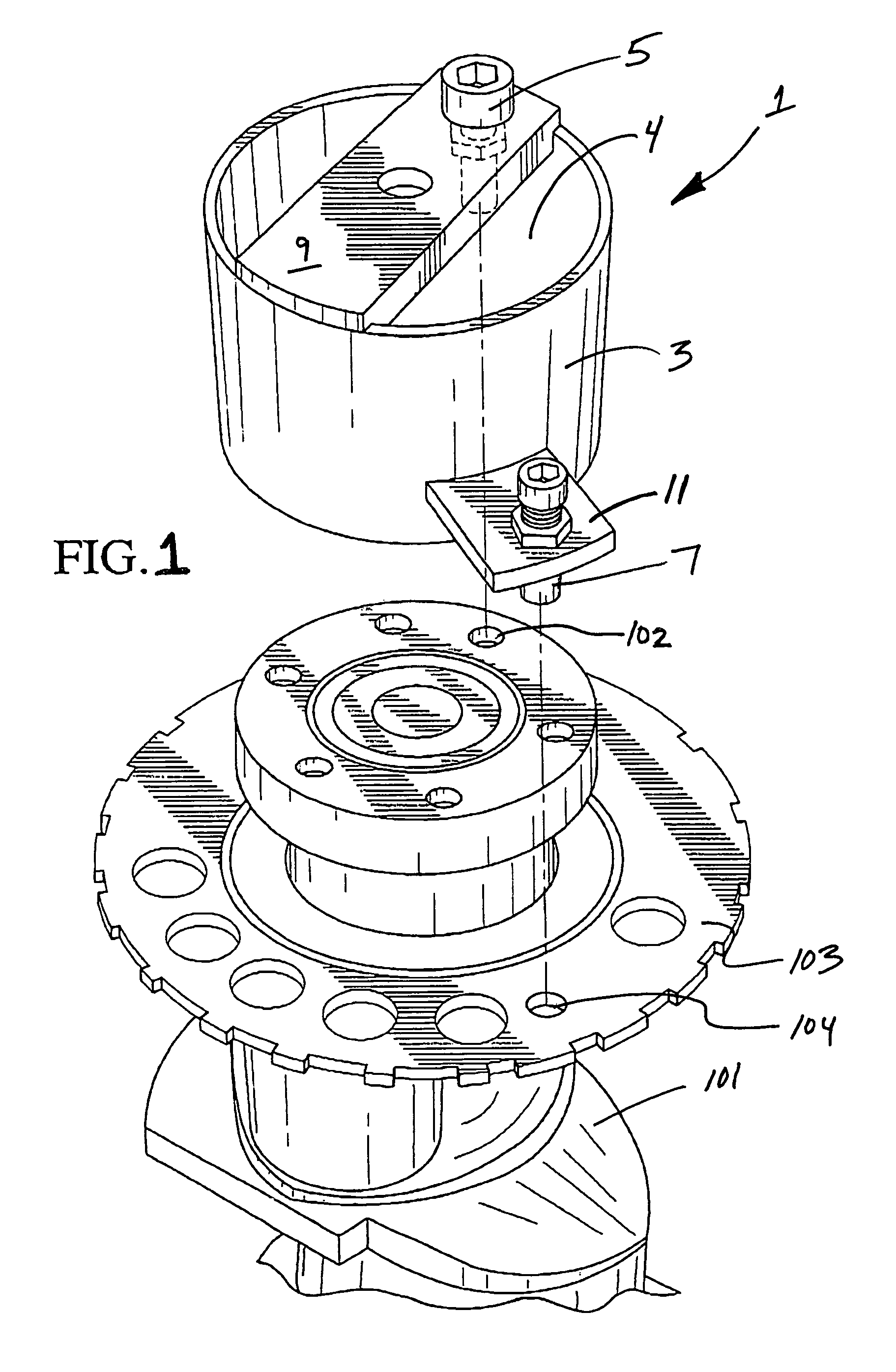
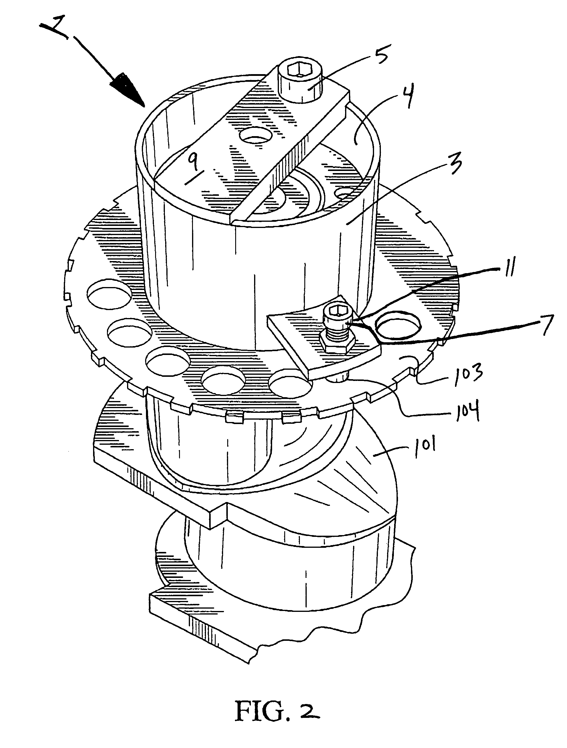
[0038]Notwithstanding the above features, the embodiment of tool 1 illustrated in FIGS. 1 and 2 is specifically configured for use with certain General Motors™ engine parts, including those installed on General Motors™ Generation III Engines including the 4.8 L, LR4, 5.3 / LM7, 5.7 LS1, and 6.0 LQ4. In this regard, FIGS. 1 and 2 illustrate a tool 1 in which the spatial orientations and dimensions of first and second alignment mechanism 5 and 7 are optimized for installation and phase calibration of such General Motors™ engine parts. In this regard, it is noted that crankshaft 101 and reluctor ring 103 each include a uniquely sized and located aperture for which alignment mechanisms 5 and 7 have been specifically located and configured.

[0039]As such, in order to install reluctor ring 103 on crankshaft 101, tool 1 is simply oriented such that alignment mechanism 7 registers with uniquely sized reference aperture 104 (an 8 mm aperture), and so that alignment mechanism 5 registers with ap...


PUM

PropertyMeasurementUnit
spatial distanceaaaaaaaaaa
diameteraaaaaaaaaa
shapeaaaaaaaaaa

Abstract

The present invention concerns an apparatus for aligning and / or installing reluctor rings on crankshafts. The apparatus include a tool body having first and second alignment mechanisms which register with crankshaft and reluctor ring apertures for aligning the reluctor rings on the crankshafts in a correct phase orientation for proper ignition timing.

Description

FIELD OF THE INVENTION[0001]This invention relates to tools for aligning and / or installing reluctor rings on a crank shaft. In at least one preferred embodiment, this invention relates to a tool having at least first and second alignment mechanisms for aligning a reluctor ring in a correct phased position on a crankshaft.BACKGROUND OF THE INVENTION[0002]In the field of automotive repair there is an occasional need for the removal and reinstallation of a reluctor ring. The reluctor ring is typically attached to the crankshaft for the purpose of controlling cylinder timing. In a conventional automotive engine, the reluctor ring provides information about the rotational position and speed of the crankshaft in order to signal the need and / or timing of a spark in appropriate cylinders (i.e. to trigger ignition thereof). In such electronic ignition systems the current of a sensor circuit, in conjunction with the reluctor ring, is intermittently broken by the teeth rotating on the cranksha...

Claims


Application Information

Patent Timeline
Patent Type & Authority Patents(United States)
IPC IPC(8): B23P17/00
CPCB25B27/00B25B27/0035Y10T29/17F01L2800/17Y10T29/49286F01L2103/01F01L2303/01
Inventor ERIKSSON, LARS
Owner GOODSON MFG
Why Eureka
Try Eureka