Bypass seal for plate heater matrix

Active Publication Date: 2017-12-28
HANON SYST
View PDF5 Cites 2 Cited by
  • Summary
  • Abstract
  • Description
  • Claims
  • Application Information

AI Technical Summary

Benefits of technology

[0007]In concordance with the instant disclosure, an improved and simplified core for a heat exchanger, the co

Problems solved by technology

For a heat exchanger, if the second fluid does not go through the second fluid flow path, but bypasses the matrix, this has a negative effect on the overall thermal performance of the heat exchanger.
For water cooled charge air coolers, where the efficiencies range from 80-95% and the charge air is desired to be cooled down close to an ambient temperature this is a significant issue.
However this configuration is problematic, as independent fasteners increase complexity, and adhesives

Method used


Image

  • Bypass seal for plate heater matrix
  • Bypass seal for plate heater matrix
  • Bypass seal for plate heater matrix

Examples


Embodiment Construction

[0023]The following detailed description and appended drawings describe and illustrate various embodiments of the invention. The description and drawings serve to enable one skilled in the art to make and use the invention, and are not intended to limit the scope of the invention in any manner. In respect of the methods disclosed, the steps presented are exemplary in nature, and thus, the order of the steps is not necessary or critical.

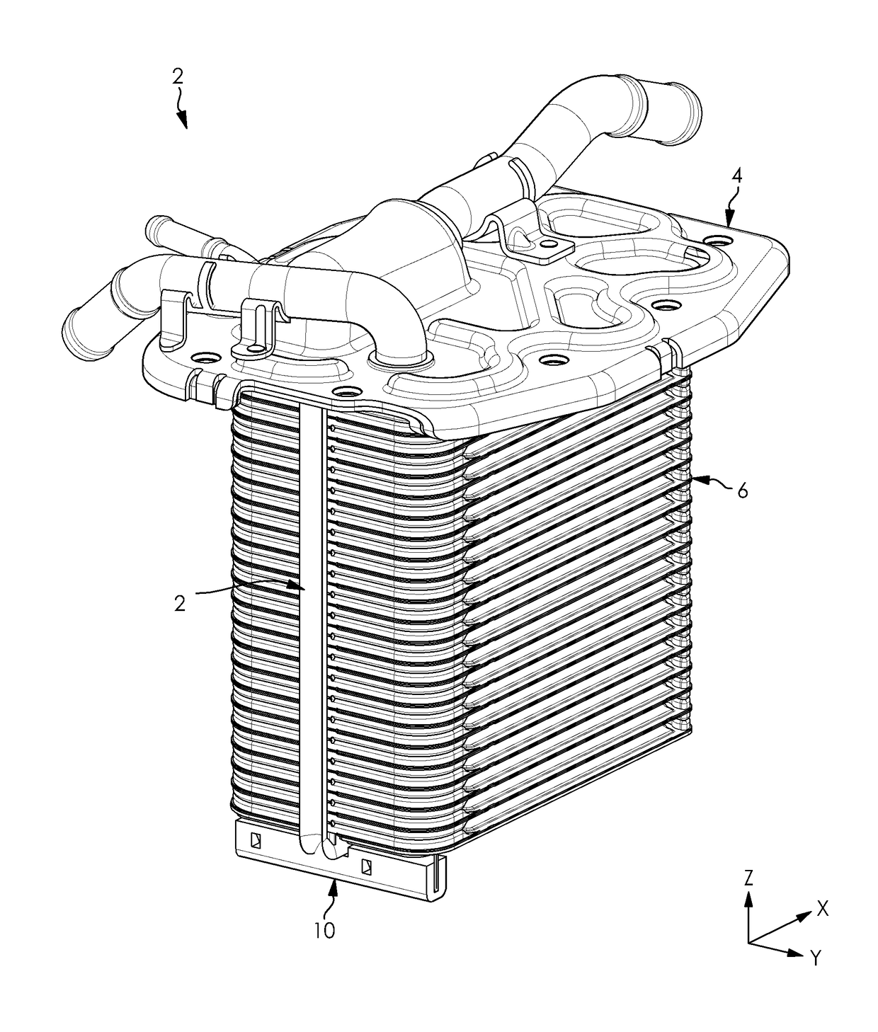
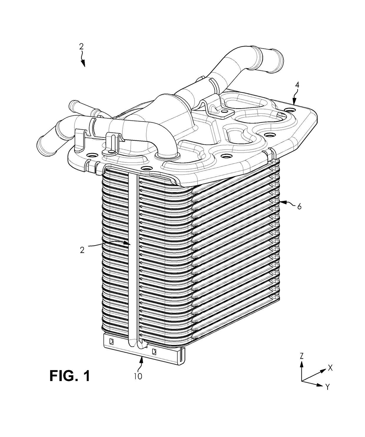
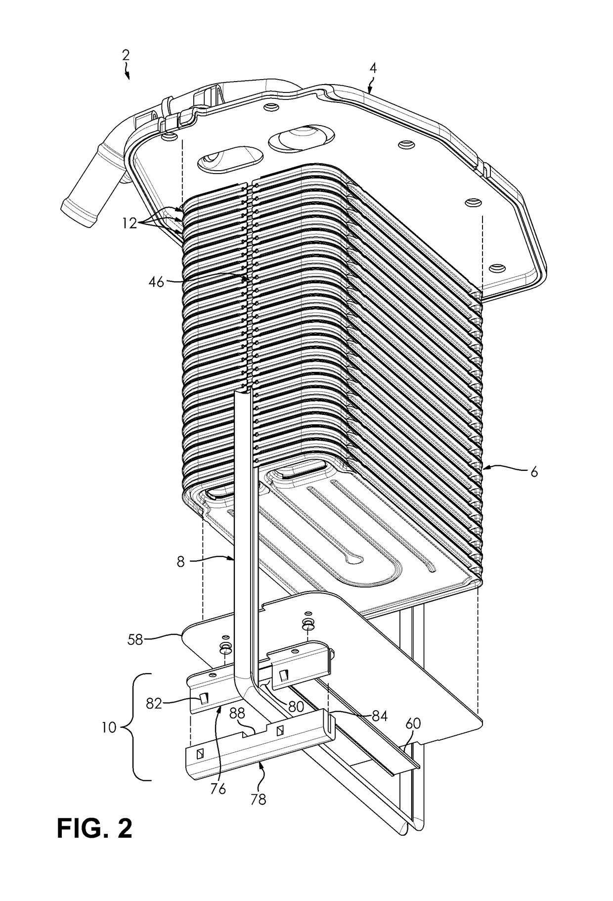
[0024]FIGS. 1-7 show a heat exchanger 2 for a motor vehicle according the instant disclosure. The heat exchanger 2 comprises a header, a core 6, a seal 8, and a support. The heat exchanger 2 also includes a housing coupled to the header and configured to enclose the core 6, the seal 8, and the support structure when the heat exchanger 2 is assembled. However, the housing has been removed in the figures for the sake of clearly illustrating the internal configuration of the heat exchanger 2 including the core 6, the seal 8, and the support.

[0025]In the ...


PUM


Abstract

A heat exchanger for a motor vehicle includes a seal and a core. The core includes a first groove formed in a first side and a second groove formed in an opposing second side. The first groove and the second groove are each configured to receive a portion of the seal to secure the seal to the core. The seal includes a cross member and a pair of uprights extending from opposing ends of the cross member, wherein the cross member and the uprights each include a sealing element. The uprights further include a rail extending from the upright and configured to be received in the groove of the core. The core further includes an integrated shear panel formed at opposing ends thereof.

Description

FIELD OF THE INVENTION[0001]The invention relates to a heat exchanger for a motor vehicle, and more particularly, to a core and seal for a heat exchanger.BACKGROUND[0002]Heat exchangers are commonly used in motor vehicles as a means of transferring thermal energy between fluids. A heat exchanger may include a core having a first fluid flow path and a second fluid flow path, wherein the first fluid flow path is fluidly separated, and in thermal communication with the second fluid flow path to facilitate a transfer of thermal energy therebetween. For example, the first fluid flow path may comprise a plurality of tubes or plates through which a first fluid flows, and second fluid flow path may comprise a matrix of passages which are formed intermediate to the tubes or plates of the first fluid flow path, wherein thermal energy is transferred through the walls of the tubes or plates from the first fluid to a second fluid.[0003]For maximum efficiency, it is imperative to ensure that an e...

Claims


Application Information

Patent Timeline
IPC IPC(8): F28D9/00F28F9/02
CPCF28D9/0093F28F9/0219F28F9/02F02B29/0462F28D9/0043F28D2021/0082F28F2230/00F28F2280/04F28F2265/32Y02T10/12F28D9/005F28F3/10F28F3/12F28D2021/008F28F2275/06
Inventor SOMHORST, LEOYOO, SEOK JONGJOYCE, STEPHENSTACH, KAMIL
Owner HANON SYST
Why Eureka
Try Eureka