
Systems and methods for powered wheelchair personal transfer

Active Publication Date: 2018-08-02
UNIVERSITY OF PITTSBURGH +2
View PDF4 Cites 3 Cited by
  • Summary
  • Abstract
  • Description
  • Claims
  • Application Information

AI Technical Summary

Benefits of technology

This patent is about an improved system for transferring patients from a bed to a rollable chair. The system includes a powered wheelchair that works with a hospital bed that has a built-in conveyor. The wheelchair and bed move coordinatedly to make the transfer easier and minimize the physical effort required by the patient and caregivers. The system also includes a new transfer device for users of electric powered wheelchairs that reduces environmental and equipment complications. Overall, the system automates the transfer process, saves time, minimizes staff involvement, and decreases caregiver risk.

Problems solved by technology

Transferring a person with a disability (PwD) between a bed and a wheelchair—or standing position, commode, chair, walker, and / or toilet—can be a labor intensive and time consuming task.
In some cases, it can take multiple people to perform the transfer and can cause injury (both acute and cumulative) to the PwD, the caregiver, and / or the transfer equipment, particularly if errors are made during transfer (e.g., if the chair is mis-positioned or the brakes are not engaged).
Other risks of PwD transfer include fear, loss of dignity, and increased dependence on others.
For PwDs who need assistance with transfers, there are not a lot of good options.
For example, overhead sling lifts require extensive installation that may not be suitable for homes or buildings with structural deficiencies or low ceilings; floor-based sling lifts have issues with caregiver manipulation and ease of use; and gantry lifts are difficult to move and store due to their size.
Research and experience suggest that caregivers and PwDs are unsatisfied with current patient transfer technology, and are concerned that their lifestyle is impaired by the lack of appropriate technologies or that it will negatively affect them and their caregivers in their futures.

Method used


Image

  • Systems and methods for powered wheelchair personal transfer
  • Systems and methods for powered wheelchair personal transfer
  • Systems and methods for powered wheelchair personal transfer

Examples


Embodiment Construction

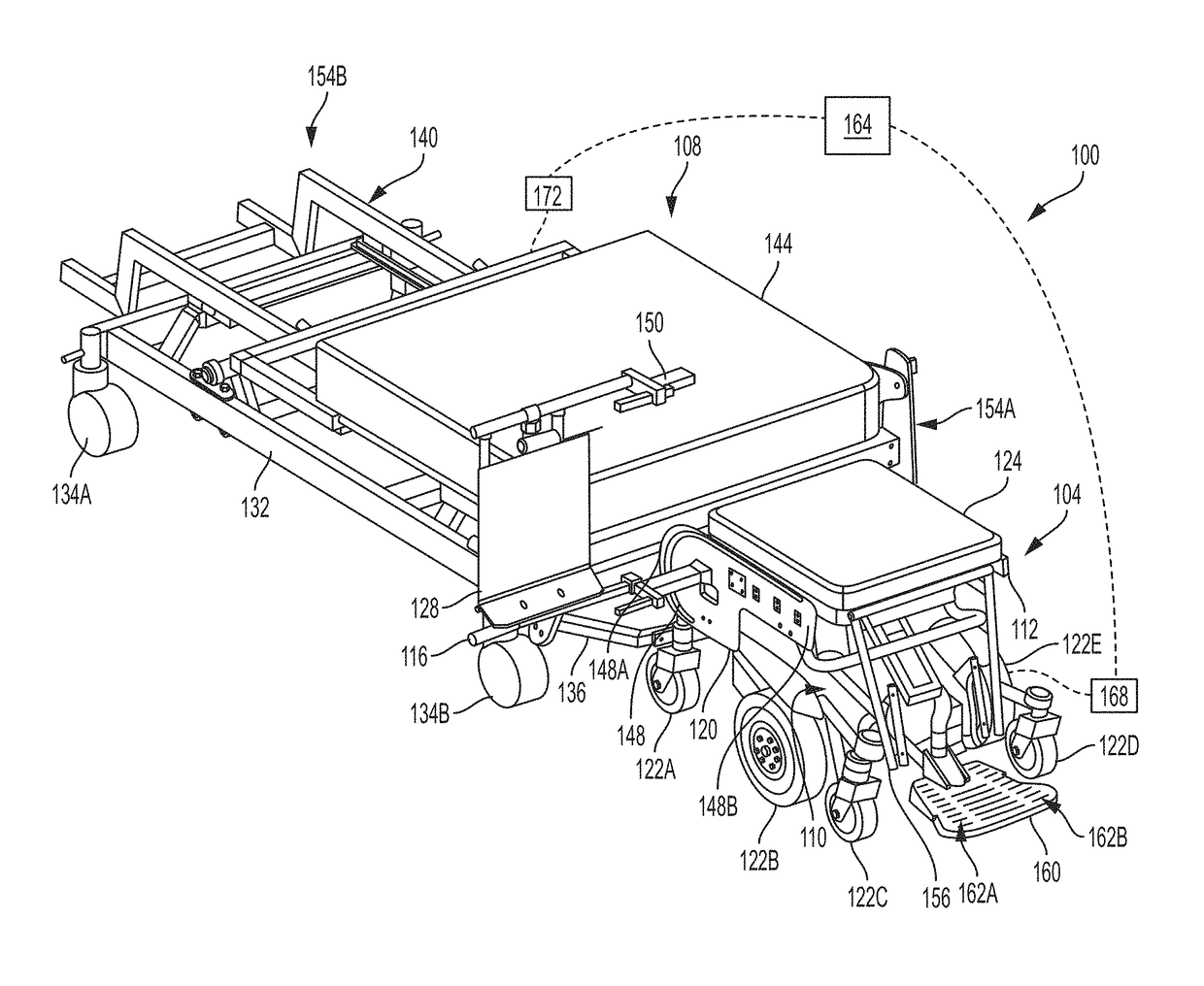
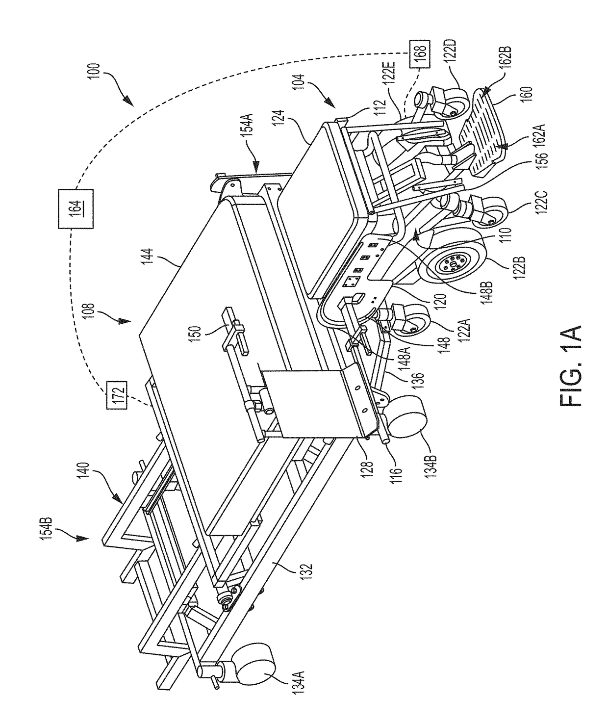
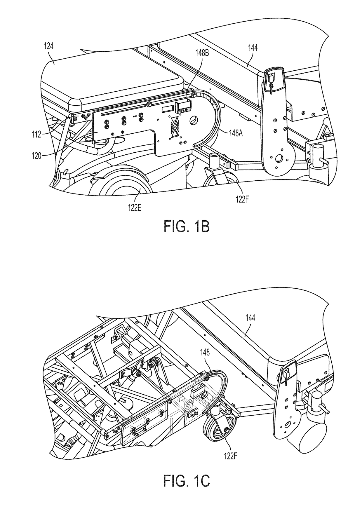
[0038]FIG. 1A is an isometric view of a patient transfer system 100 including a rollable chair 104 (also depicted separately in FIG. 1F) and a bed 108, according to an illustrative embodiment of the invention. The rollable chair 104 includes a first frame 112, a second frame 116 coupled to the first frame 112, and a third frame 120 coupled to the first frame 112. The frames 112, 116, 120 can be made of, for example, steel, aluminum, another metal or metal alloy, or a composite material such as carbon fiber. The rollable chair 104 also includes several wheels (e.g., wheels 122A-F as shown in FIGS. 1A-1E). The base unit 110 can be a commercially available pedestal seat powered wheelchair base. In some embodiments, the wheels 122A, 122F (rear wheels) help to guide the rollable chair 104 toward the bed 108. In some embodiments, the wheels 122B, 122E (drive wheels) are larger and help to power the rollable chair 104. In some embodiments, the wheels 122C and 122D (front wheels) help to gu...


PUM


Abstract

The invention includes methods and apparatuses for patient transfer from a rollable chair to a bed and back. A rollable chair includes a first frame having a seat; a second frame coupled to the first frame, the second frame having a backrest configured to move relative to the first frame; and a third frame coupled to the first frame, the third frame having a track having a curvilinear length configured to allow the first frame to rotate and to translate relative to the third frame. A bed includes a chair-receiving frame configured to couple to the first frame of the rollable chair. The rollable chair and the bed work in tandem to transfer a patient, for example using coordinated, automated motions.

Description

RELATED APPLICATIONS[0001]This application claims the benefit of U.S. Provisional Patent Application Ser. No. 62 / 452,542 filed Jan. 31, 2017, entitled “Systems and Methods for Powered Wheelchair Personal Transfer,” the contents of which are hereby incorporated herein by reference in their entirety.GOVERNMENT RIGHTS[0002]This invention was made with government support under Contract Nos. B9269-L and B9250C, awarded by the U.S. Dept. of Veterans Affairs, and Contract No. EEC-1560174S, awarded by the National Science Foundation. The U.S. Government may have certain rights in the invention.FIELD OF THE INVENTION[0003]The invention relates generally to devices, apparatuses, systems and methods for patient transfer. More specifically, the invention relates to patient transfer from a rollable powered wheelchair to a bed and back.BACKGROUND[0004]Transferring a person with a disability (PwD) between a bed and a wheelchair—or standing position, commode, chair, walker, and / or toilet—can be a l...

Claims


Application Information

Patent Timeline
IPC IPC(8): A61G7/16A61G7/10A61G7/002
CPCA61G7/165A61G7/1034A61G7/1069A61G7/002A61G7/1001A61G7/1048A61G7/1059A61G2203/30A61G5/04A61G5/1056A61G5/1067A61G5/1075A61G7/053A61G7/1032A61G7/1065A61G2203/80
Inventor COOPER, RORY ALANBECKSTROM, DAVIDCURATOLO, RAYMOND A.GRINDLE, GARRETTKOVACSICS, RICHARD
Owner UNIVERSITY OF PITTSBURGH
Learn More