Apparatus for producing rubber strip

Inactive Publication Date: 2006-03-16
SUMITOMO RUBBER IND LTD
View PDF12 Cites 4 Cited by
  • Summary
  • Abstract
  • Description
  • Claims
  • Application Information

AI Technical Summary

Benefits of technology

[0006] It is a main object of the present invention to provide an apparatus for producing rubber strips capable of simultaneously forming at

Problems solved by technology

The conventional method as a problem that the number of

Method used


Image

  • Apparatus for producing rubber strip
  • Apparatus for producing rubber strip
  • Apparatus for producing rubber strip

Examples


Embodiment Construction

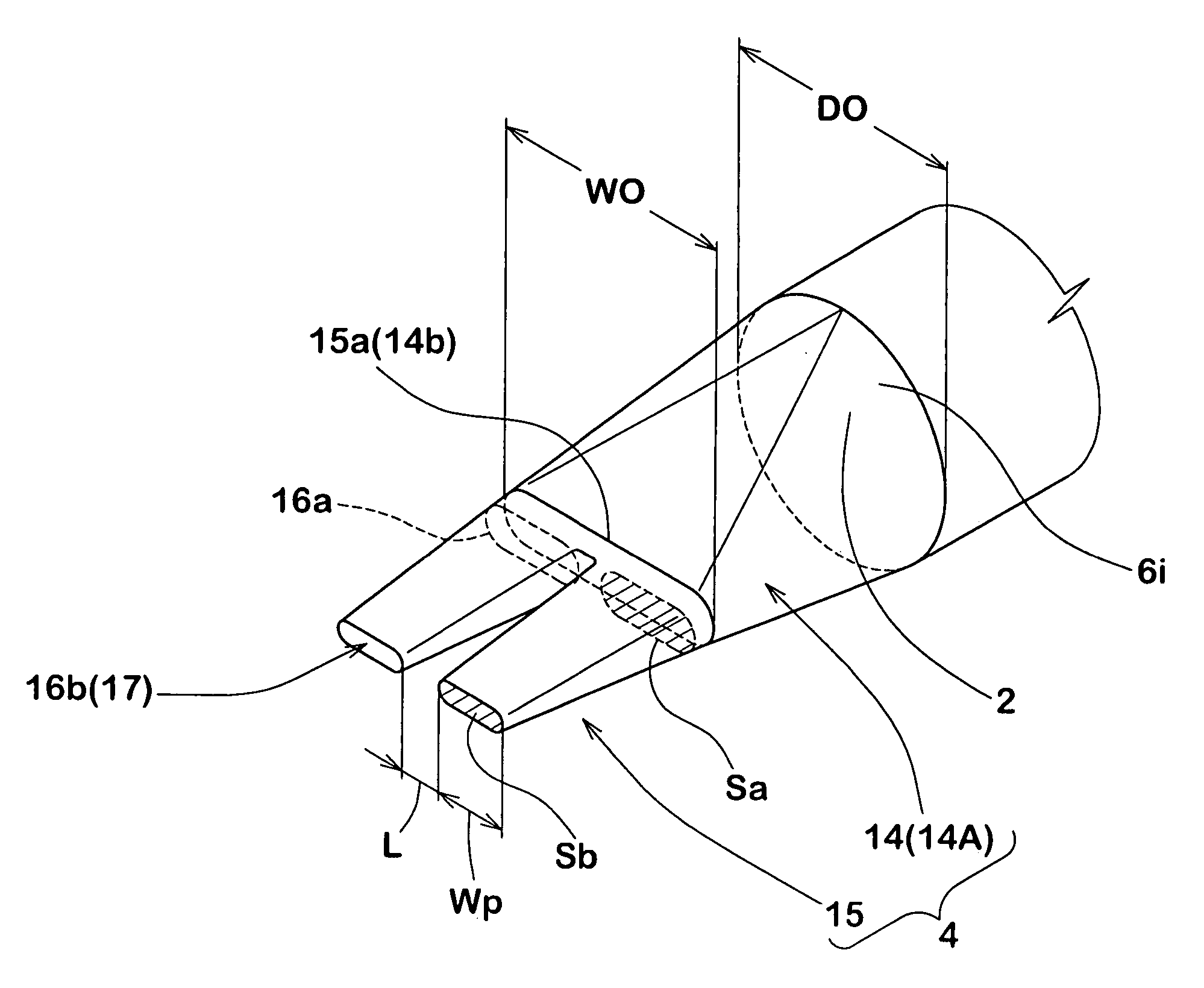
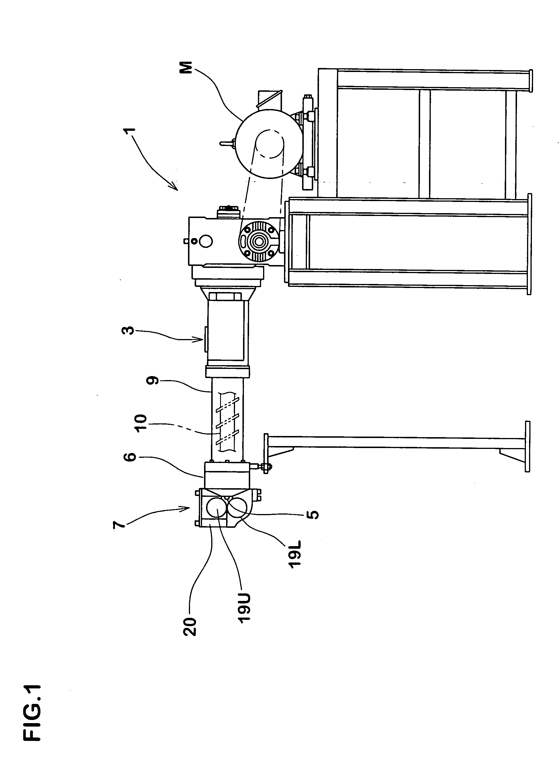
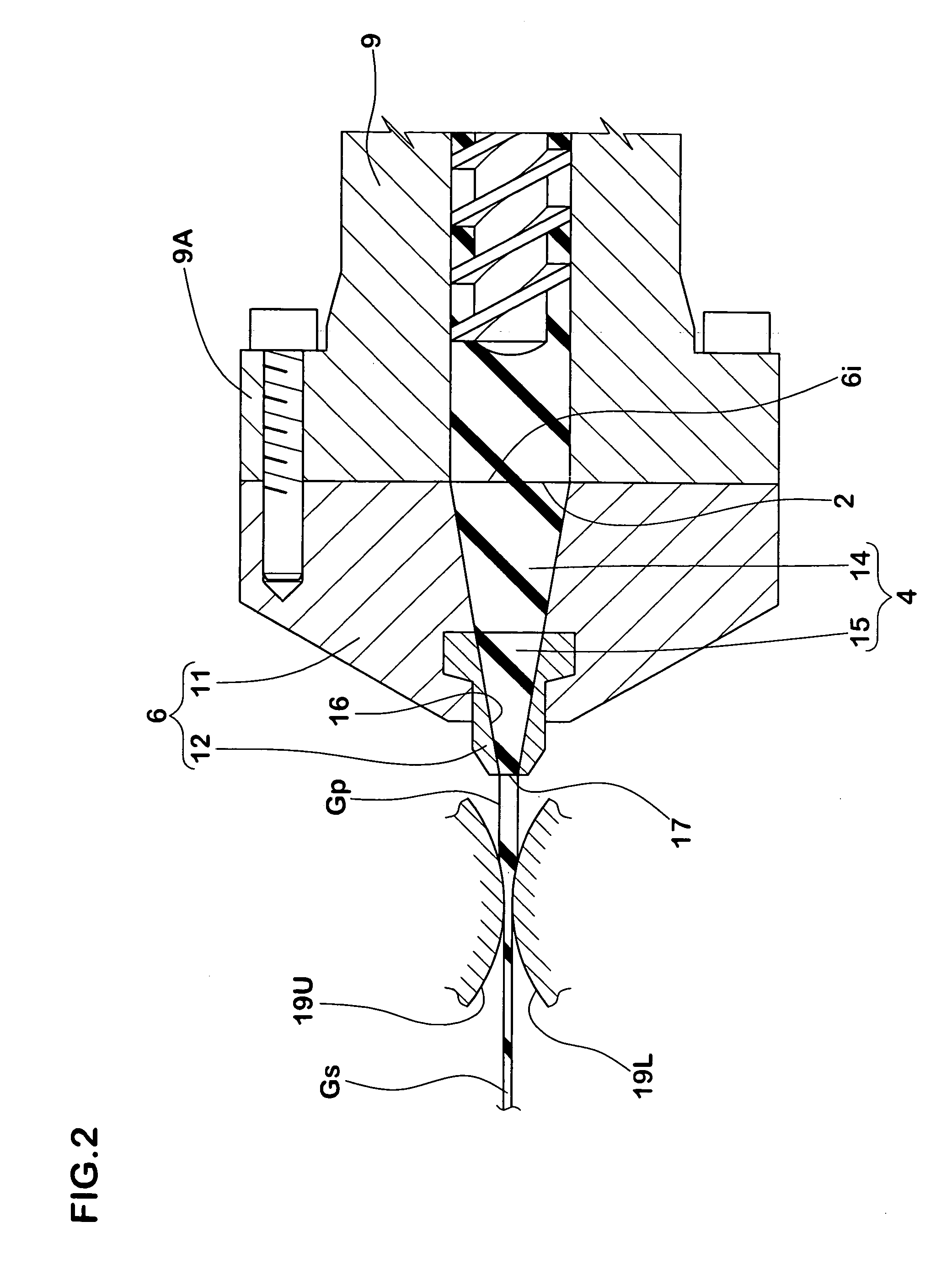
[0019] In FIGS. 1 and 2, an apparatus 1 for producing rubber strips (simply “the apparatus”, hereinafter in some cases) comprises an extruder 3 for extruding compounded rubber into at least two preliminary rubber strips Gp each having a preliminary cross sectional shape, and a calendar head 7 having a pair of calendar rollers 19U, 19L for simultaneously forming the preliminary rubber strips Gp into at least two rubber strips Gs each having a finished cross sectional shape.

[0020] The apparatus 1 of this embodiment is used for forming a tire rubber component by the dual wind method. As shown in FIG. 6, the apparatus 1 of the embodiment can produce two rubber strips Gs each having a strip width Ws of from 5 mm to 30 mm and a strip thickness Ts of from 0.5 mm to 2.0 mm.

[0021] The two rubber strips Gs are supplied to the tire former having a cylindrical surface (not shown) at relatively high temperature, i.e., without through a cooling step, and are wound around the former spirally. wi...


PUM

PropertyMeasurementUnit
Distanceaaaaaaaaaa
Distanceaaaaaaaaaa
Shapeaaaaaaaaaa

Abstract

The present invention relates to an apparatus for producing at least two rubber strips comprising an extruder for extruding compounded rubber into at least two preliminary rubber strips each having a preliminary cross sectional shape, and a pair of calendar rollers for simultaneously forming the preliminary rubber strips into at least two rubber strips each having a finished cross sectional shape.

Description

FIELD OF THE INVENTION [0001] The present invention relates to an apparatus for producing rubber strips capable of simultaneously and precisely forming a plurality of rubber strips from one extruder. DESCRIPTION OF THE BACKGROUND ART [0002] In a pneumatic tire, in order to sufficiently exhibit characteristics of its various portions, a tread rubber component, a sidewall rubber component, a clinch rubber component and an inner liner rubber component are made of different compounds. Further, when the pneumatic tire is to be produced, the rubber components mentioned above are extruded into different cross sectional shapes and are supplied to a tire former. [0003] In recent years, a strip wind method is proposed to form the rubber components. According to the strip wind method, as shown in FIG. 7(A) for example, a ribbon-like unvulcanized rubber strip “a” is continuously wound around a tire former (not shown) spirally, thereby obtaining a rubber component b having desired cross sectiona...

Claims


Application Information

Patent Timeline
IPC IPC(8): B29C47/12B29C48/07B29C48/30B29C48/305B29C48/35
CPCB29C47/0019B29C47/0021B29C47/003B29L2030/002B29C47/32B29C47/70B29C47/30B29C48/07B29C48/08B29C48/12B29C48/345B29C48/35B29C48/695
Inventor HAYASHI, NORIOONIMATSU, HIROYUKI
Owner SUMITOMO RUBBER IND LTD
Why Eureka
Try Eureka