
Developer, process cartridge, and image forming apparatus

Active Publication Date: 2008-04-17
FUJIFILM BUSINESS INNOVATION CORP
View PDF6 Cites 20 Cited by
  • Summary
  • Abstract
  • Description
  • Claims
  • Application Information

AI Technical Summary

Benefits of technology

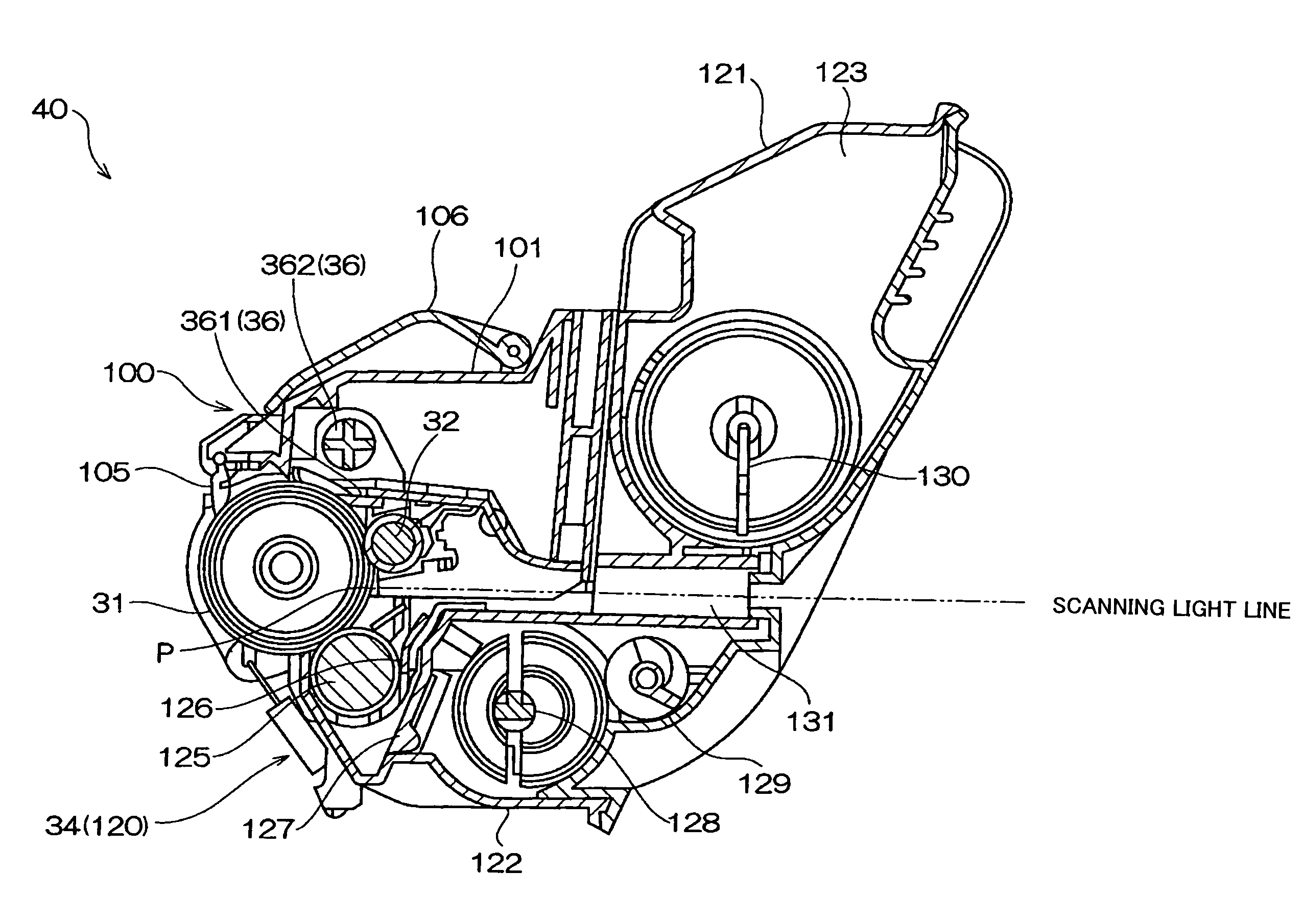
[0011]Namely, the invention can provide a developer, a process cartridge and an image forming apparatus that ensure a developer storage capacity without reducing a space for the developer in the developing device while providing both long life and a small apparatus size, and that can also maintain a stable image quality by substantially preventing occurrence of non-uniformity in color concentration until the toner in the process cartridge is exhausted.

Problems solved by technology

While the two-component developing method has widely been used for development since it is advantageous for high speed processing, it involves disadvantages such as deterioration of the developer due to adhesion of the toner on the surface of a carrier and a large size of the developing device since the mixing ratio of the toner to the carrier should be kept constant so that the toner concentration in the developer does not decrease due to only the toner being consumed in this method.
Consequently, the cost of controlling the toner density becomes high.
However, while so-called long life is urgently required for increasing the number of printing sheets (the number of copying sheets) per process cartridge in addition to the requirement for more compactness in recent years, a space for accommodating the developer is further reduced by making the process cartridge small.
The developing device contains a developer storage portion for storing developer, so that the storage portion for the developer must be reduced, and it has been difficult to reduce the size of the apparatus while maintaining the developer storage capacity of the developer storage portion.

Method used


Image

  • Developer, process cartridge, and image forming apparatus
  • Developer, process cartridge, and image forming apparatus
  • Developer, process cartridge, and image forming apparatus

Examples


example 1

[0113]Using a Henschel mixer, 51.25 parts by weight of polyester resin (cross-linked polyester mainly containing propylene oxide adduct of bisphenol A and terephthalic acid; weight-average molecular weight of THF-soluble fraction: 12,000; Tg=58.5° C.), 45.0 parts by weight of a magnetic powder (saturation magnetization: 82 Am2 / kg; residual magnetization: 5.5 Am2 / kg; coercive force: 4.8 kA / m to 398 kA / m), 3.0 parts by weight of polypropylene wax (weight-average molecular weight: 3,000; melting point: 126° C.), and 0.75 part by weight of charge controlling agent (trade name T-77, manufactured by Hodogaya Chemical Co., Ltd.) are mixed. The resultant mixture is kneaded with heating using an extruder adjusted at 160° C.

[0114]After cooling, the kneaded mixture is crushed and pulverized followed by classification to obtain a classified toner having a volume average particle diameter of 7.8 μm and a proportion of the number of particles having a particle diameter of 4 μm or less of 15%. To ...

example 2

[0117]Toner B is obtained and evaluated in the same manner as in Example 1, except that the classified toner is prepared so as to have a volume average particle diameter of 9.0 μm and a proportion of the number of particles having a particle diameter of 4 μm or less of 10%, the silicone oil-treated silica particle is changed to have an average particle diameter of 0.10 μm, and the addition amount the silicone oil-treated silica particle is changed to be 0.8 parts by weight. Results of evaluations thereof are shown in the following Table 2. The AR value of the toner B is 9.8.

example 3

[0118]Toner C is obtained and evaluated in the same manner as in Example 1, except that the classified toner is prepared so as to have a volume average particle diameter of 7.0 μm and a proportion of the number of particles having a particle diameter of 4 μm or less of 16%. Results of evaluations thereof are shown in the following Table 2. The AR value of the toner C is 5.1.


PUM


Abstract

The invention provides a developer having at least a toner, an aeration ratio (AR) of the developer measured by a powder rheometer being in a range of about 5.0 to about 10.0. It is preferable that the developer further contains an external additive of silica particles having a small diameter. The invention further provides a process cartridge having at least: a photoreceptor; and a developing device that comprises plura developer storage portions and that makes visible a latent image formed on the photoreceptor by using the developer. The invention further provides an image forming apparatus having at least the process cartridge.

Description

BACKGROUND OF THE INVENTION[0001]1. Field of the Invention[0002]The present invention relates to a developer used for an image forming apparatus such as a copying machine or printer, and a process cartridge and an image forming apparatus used therefor.[0003]2. Description of the Related Art[0004]A number of electrophotographic processes are known in the art. In the electrophotographic process, a fixed image is formed through a plurality of steps comprising electrically forming a latent image by various methods on a photoreceptor utilizing a photoconductive material, developing the latent image using a toner, transferring the toner latent image on the photoreceptor onto a transfer object such as a sheet of paper with or without interposition of an intermediate transfer apparatus, and fixing the latent image by heating, compressing or heating with compression, or with a vapor of a solvent. If necessary, toner remaining on the photoreceptor is cleaned off by various methods, and the af...

Claims


Application Information

Patent Timeline
IPC IPC(8): G03G21/16G03G21/18G03G9/00G03G9/08
CPCG03G9/0819G03G9/09708G03G2221/183G03G9/09725G03G9/09716
Inventor TAKEDA, TOMOHIROINOUE, TOYOFUMIISHIZUKA, DAISUKE
Owner FUJIFILM BUSINESS INNOVATION CORP
Learn More