Image decoding apparatus, image decoding program, image decoding method, image encoding apparatus, image encoding program, and image encoding method

a motion detection and image technology, applied in the field of image decoding apparatus, can solve the problems of enormous computational complexity of the resolution enhancement process for motion detection, and the difficulty of accurately performing motion detection between lr images and hr images, so as to improve the image quality of reconstructed high-resolution images, improve the accuracy of motion detection, and reduce the processing load of motion search.

Inactive Publication Date: 2006-06-15
NTT DOCOMO INC
View PDF8 Cites 107 Cited by
  • Summary
  • Abstract
  • Description
  • Claims
  • Application Information

AI Technical Summary

Benefits of technology

[0009] The present invention has been accomplished in order to solve the above problem and an object of the invention is to provide image decoding apparatus, image decoding program, image decoding method, image encoding apparatus, image encoding program, and image encoding method capable of improving the accuracy of the motion detection between images, while reducing the computational complexity for the image resolution enhancement process.
[0037] The present invention described above improves the accuracy of the motion detection between images and improves the image quality of the reconstructed high-resolution image. Since the processing load of the motion search is reduced, the computational complexity is reduced for the image resolution enhancement.

Problems solved by technology

In the conventional super resolution technology, it is difficult to accurately perform the motion detection between the LR images and HR image because of influence of coding noise and sampling blur of the LR images, uncertainty of the assumption model, etc. in the resolution enhancement process of generating the HR image from a plurality of images.
In addition, the resolution enhancement process requires enormous computational complexity for the motion detection between images and for the optimization process.

Method used


Image

  • Image decoding apparatus, image decoding program, image decoding method, image encoding apparatus, image encoding program, and image encoding method
  • Image decoding apparatus, image decoding program, image decoding method, image encoding apparatus, image encoding program, and image encoding method
  • Image decoding apparatus, image decoding program, image decoding method, image encoding apparatus, image encoding program, and image encoding method

Examples


Embodiment Construction

[0060] Embodiments of the present invention will be described with reference to FIGS. 2 to 12.

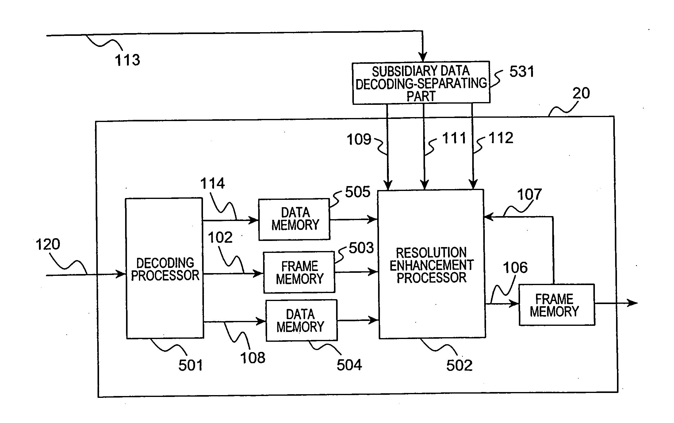
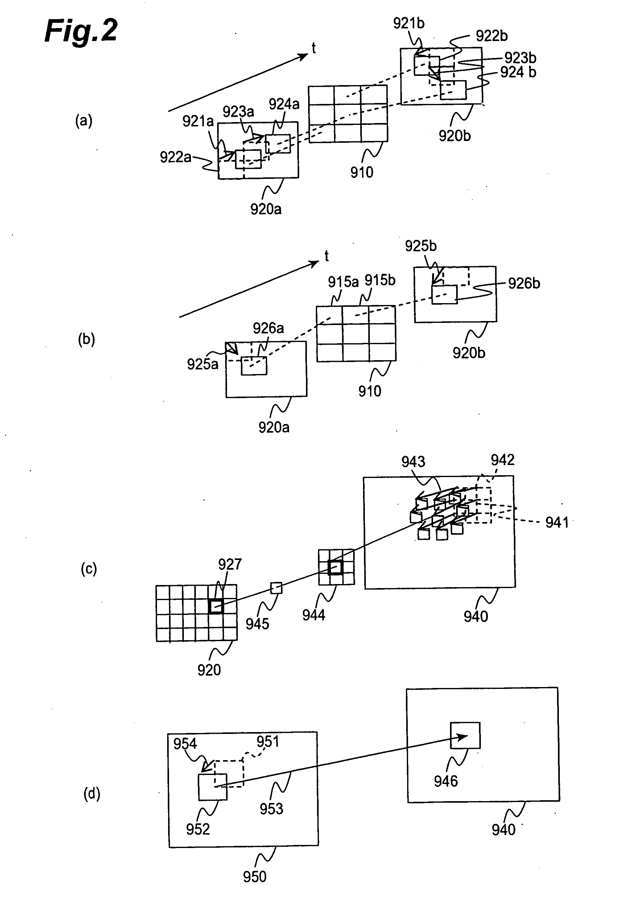
[0061]FIG. 2 is an illustration to illustrate motion vectors, among data contained in some kinds of motion information. FIGS. 3 to 5 are illustrations to illustrate configurations of an encoding apparatus according to the present invention, and FIGS. 6 and 7 illustrations to illustrate configurations of a decoding apparatus according to the present invention. FIG. 8 is an illustration to illustrate a data format configuration of subsidiary data in the present invention. FIGS. 9 to 11 are illustrations to illustrate a processing flow of encoding, a processing flow of super-resolution image generation, and a processing flow of decoding, respectively. FIG. 12 is an illustration to illustrate a data storage medium storing a program for implementing an image encoding process or image decoding process by a computer system.

[0062] The subsidiary data in the present invention has subsidiary motion...


PUM


Abstract

An image decoding apparatus has a video data decoder for receiving and decoding encoded video data to acquire a plurality of reconstructed images; a subsidiary data decoder for receiving and decoding subsidiary data to acquire subsidiary motion information; and a resolution enhancer for generating motion vectors representing time-space correspondences between the plurality of reconstructed images, based on the subsidiary motion information acquired by the subsidiary data decoder, and for generating a high-resolution image with a spatial resolution higher than that of the plurality of reconstructed images, using the generated motion vectors and the plurality of reconstructed images acquired by the video data decoder.

Description

BACKGROUND OF THE INVENTION [0001] 1. Field of the Invention [0002] The present invention relates to image decoding apparatus, image decoding program, image decoding method, image encoding apparatus, image encoding program, and image encoding method. [0003] 2. Related Background Art [0004] A well-known technology is a super resolution technique (the term “super resolution” will be referred to hereinafter as SR) of generating a high-resolution image (the term “high resolution” will be referred to hereinafter as HR) from a plurality of low-resolution images (the term “low resolution” will be referred to hereinafter as LR) reconstructed through decoding of encoded video data (e.g., “C. A. Segall et al., “High-Resolution Images from Low-Resolution Compressed Video,” IEEE Signal Processing Magazine, May 2003, pp. 37-48,” which will be referred to hereinafter as “Non-patent Document 1”). [0005] The SR technique permits us to generate an HR image from a plurality of LR images by modeling r...

Claims


Application Information

Patent Timeline
Patent Type & Authority Applications(United States)
IPC IPC(8): G06K9/36H04N19/50H03M7/36H04N19/103H04N19/119H04N19/137H04N19/139H04N19/176H04N19/33H04N19/423H04N19/51H04N19/577H04N19/59H04N19/593
CPCG06T5/002H04N19/59G06T5/50G06T2207/10016G06T2207/20021G06T3/4053H04N19/105H04N19/52H04N19/176H04N19/70H04N19/61H04N19/136H04N19/192H04N19/33H04N19/53H04N19/523H04N19/57G06T5/003
Inventor SUZUKI, YOSHINORIBOON, CHOONG SENGTAN, THIOW KENG
Owner NTT DOCOMO INC
Why Eureka
Try Eureka