
Antireflection film and organic light emitting device provided with the same
an anti-reflection film and light-emitting device technology, applied in non-linear optics, instruments, polarising elements, etc., can solve the problems of reducing display quality, deteriorating visibility, and deteriorating visibility and contrast ratio, so as to compensate the deterioration of visibility, the effect of strong viewing angle dependen
- Summary
- Abstract
- Description
- Claims
- Application Information
AI Technical Summary
Benefits of technology
Problems solved by technology
Method used
Image

Examples
example 1
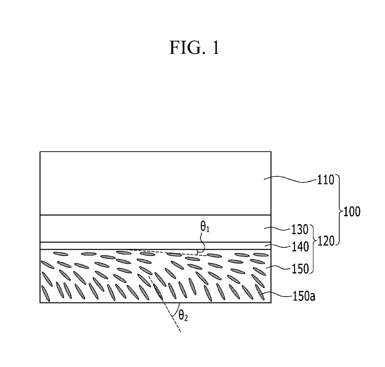
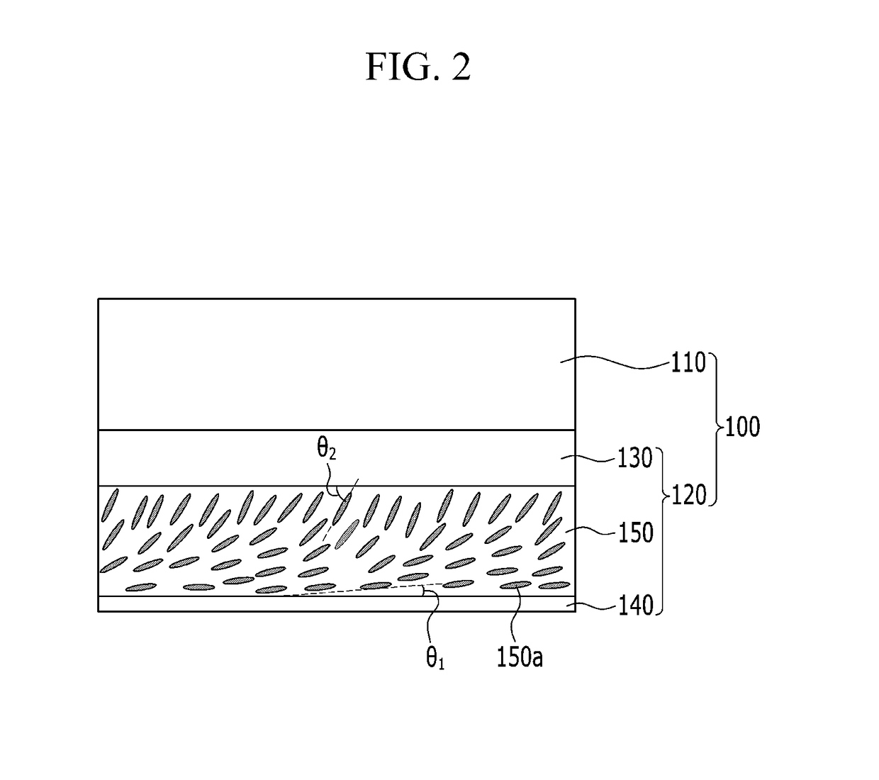
[0123]A simulation evaluation (LCD Master (Shintech Inc.)) is performed by simulation-setting of a structure formed by sequentially disposing a polarizer, a compensation film (Re=138 nm) including a liquid crystal layer, and a reflector. Herein, the liquid crystal layer of the compensation film has a bottom tilt structure (see FIG. 1) in which a tilt angle of the liquid crystals is larger from the top to the bottom. The minimum tilt angle (an upper tilt angle) is about 3° and the maximum tilt angle (a lower tilt angle) is about 37°, between which the tilt angle gradually changes. The wavelength dispersion (WD) of the liquid crystal layer (Re (450 nm) / Re (550 nm)) is 0.82. The angle of an axis of the polarizer is set at about 90° and the angle of an axis of the compensation film is set at about 45°.
example 2
[0124]A simulation condition is set according to the same method as Example 1, except the maximum tilt angle (the lower tilt angle) of the liquid crystals in the liquid crystal layer of the compensation film (Re=138 nm) is set at about 45°.
example 3
[0125]A simulation condition is set according to the same method as Example 1, except the maximum tilt angle (the lower tilt angle) of liquid crystals in the liquid crystal layer of the compensation film (Re=138 nm) is set at at about 65°.
PUM
 Abstract
Description
Claims
Application Information