
Designing a virtual preparation and a virtual gingival

a technology of virtual preparation and gingival, applied in the field of virtual preparation and virtual gingival, can solve the problems of patient temporary buildup, inability to make the final design of the restoration using the temporary design, and high cos

Active Publication Date: 2017-09-19
3SHAPE AS
View PDF13 Cites 11 Cited by
  • Summary
  • Abstract
  • Description
  • Claims
  • Application Information

AI Technical Summary

Benefits of technology

[0164]It is an advantage of the present invention that many different kinds of information, such as scan data, 3D CAD design may be used to design and finally obtain a 3D virtual model of a dental component to be inserted or arranged in the mouth of a patient, either temporarily or permanently.
[0165]Determining at least part of a surface and / or designing a feature comprises determining and / or designing the shape of the surface.
[0167]The steps of the method may be performed wholly or partly by an operator or user and / or wholly or partly performed automatically by the processing means of a computer program.
[0168]The diagnostic component can e.g. be a restoration produced because a tooth is broken, missing, should be “turned” etc.
[0169]Thus in some embodiments determining at least part of a surface not available in the 3D representation comprises virtually designing at least a part of the dental component.
[0170]In some embodiments the surface which is not available in the 3D representation is at least a part of the dental component being designed.

Problems solved by technology

It remains a problem to provide improved planning and virtual designing of a dental component, such as a restoration, a temporary restoration or a diagnostic wax-up, for a patient.
This method is very time consuming, and the final design of the restoration cannot be made using the temporary design.
This method may be faster, but it may be very uncomfortable for the patient to have the temporary build up in his mouth, and again the final design of the restoration cannot be made using the temporary design.
Thus when making the final design, the dental technician has to start all over as he cannot reuse the design he already made for the temporary restoration.
Therefore the pre-prepared teeth may have received some, typically minor, treatment, such as cleaning, polishing, minor grinding and / or the like, but the pre-prepared teeth have not been prepared for a dental restoration.

Method used


Image

  • Designing a virtual preparation and a virtual gingival
  • Designing a virtual preparation and a virtual gingival
  • Designing a virtual preparation and a virtual gingival

Examples


Embodiment Construction

[0300]In the following description, reference is made to the accompanying figures, which show by way of illustration how the invention may be practiced.

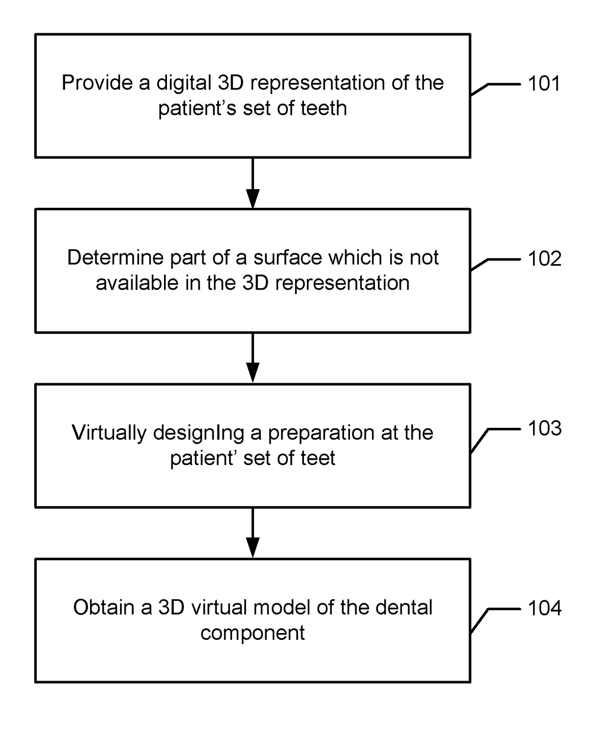
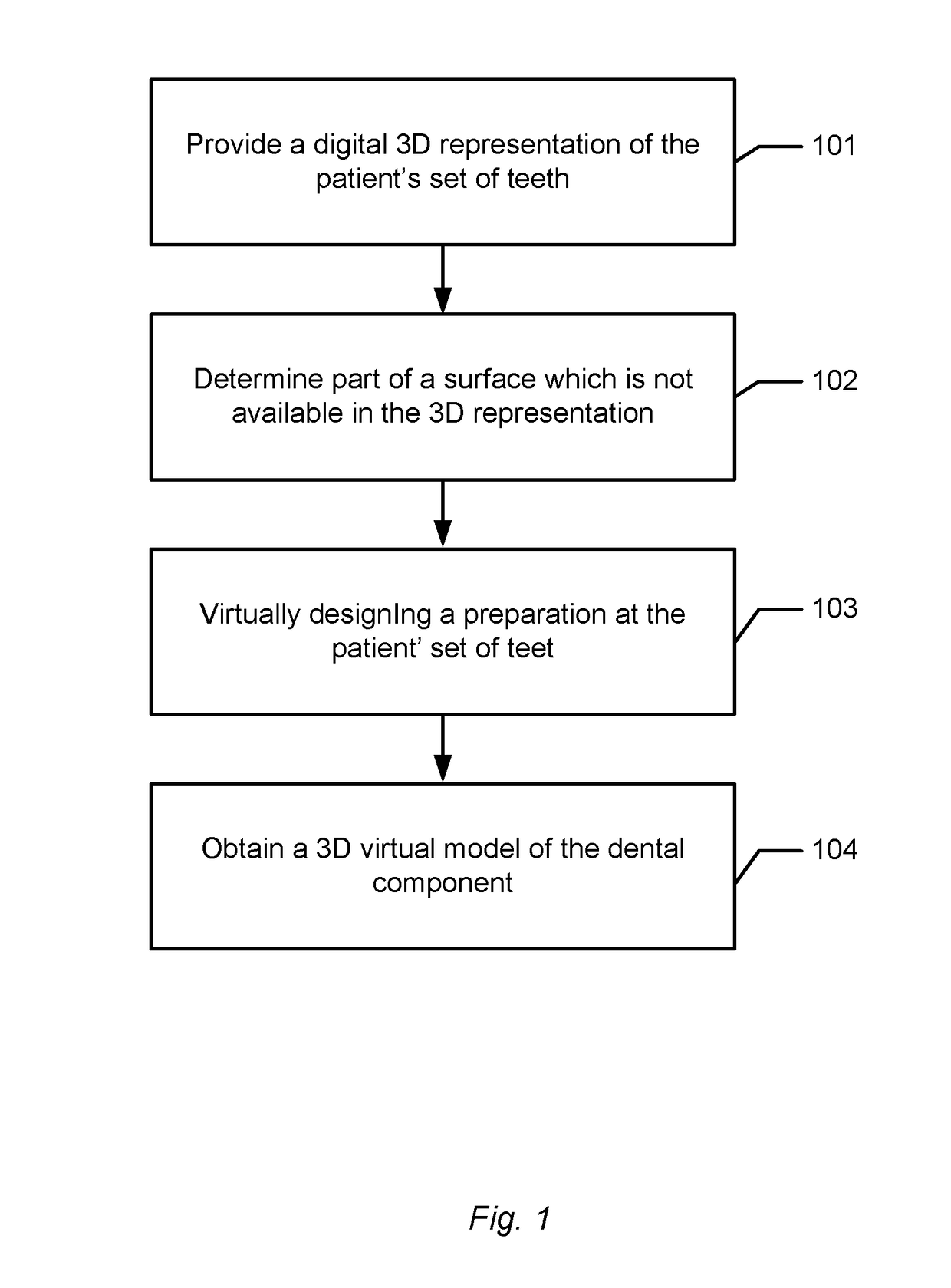
[0301]FIG. 1 shows an example of a flowchart for an embodiment of the method of designing a dental component for a region on a patient's set of teeth.

[0302]In step 101a digital 3D representation of at least the region of the patient's set of teeth is provided. The digital 3D representation is based on a 3D scan.

[0303]In step 102 at least part of a surface which is not available in the 3D representation is determined.

[0304]In step 103 a preparation is virtually designed in the region of the patient' set of teeth for the dental component.

[0305]In step 104 a 3D virtual model of the dental component is obtained.

[0306]The order of the steps may be the order as above or a different order, e.g.:

[0307]In step 101a digital 3D representation of at least the region of the patient's set of teeth is provided. The digital 3D representation is base...


PUM


Abstract

This invention generally relates to a system and a method of designing a dental component for a region on a patient's set of teeth. More particularly, the invention relates to obtaining a digital 3D representation of at least the region of the patient's set of teeth, where the digital 3D representation is based on a 3D scan.

Description

FIELD OF THE INVENTION[0001]This invention generally relates to a system and a method which can be used in relation to designing a dental component for a region on a patient's set of teeth. More particularly, the invention relates to obtaining a digital 3D representation of at least the region of the patient's set of teeth, where the digital 3D representation is based on a 3D scan.BACKGROUND OF THE INVENTION[0002]WO10105628 discloses a method for planning, visualizing, and / or optimizing dental restoration on at least a part of the pre-prepared teeth of a patient, wherein said method comprises the steps of:[0003]providing at least one 3D digital model of at least a part of the pre-prepared teeth;[0004]designing at least one dental restoration CAD model based on the 3D digital model of at least a part of the pre-prepared teeth;[0005]providing at least one 3D digital model of at least a part of the prepared teeth, where the prepared teeth are provided by preparing the pre-prepared teet...

Claims


Application Information

Patent Timeline
Patent Type & Authority Patents(United States)
IPC IPC(8): G06F17/50B33Y50/00B33Y80/00A61C13/00
CPCG06F17/50A61C13/0004B33Y50/00B33Y80/00G16H20/40G06F30/00
Inventor FISKER, RUNENONBOE, SVEN
Owner 3SHAPE AS
Learn More