Relative orientation angle calculation method and device as well as relative positioning method

a relative orientation angle and calculation method technology, applied in surveying and navigation, instruments, navigation instruments, etc., can solve the problems of radio signal decoding error at the receipt mobile device, inaccurate reception frequency of radio signal,

Active Publication Date: 2017-09-26
RICOH KK
View PDF5 Cites 52 Cited by
  • Summary
  • Abstract
  • Description
  • Claims
  • Application Information

AI Technical Summary

Benefits of technology

[0022]Compared to the conventional techniques, by utilizing the method and device for calculating a relative orientation angle according to the embodiments of the present invention, it is possible to calculate, by using the inertial sensor data of at least two mobile devices and the Doppler effect whose influence is on the radio signal sent between them, the relative orientation angle between them. That is, by employing the calculation process of a relative orientation angle according to the embodiments, it is possible to achieve the relative orientation angle calculation on the basis of the Doppler effect and the inertial sensor data only between two mobile devices, i.e., it is not necessary to use an additional mobile device or to introduce other auxiliary parameters. As a result, the method and device for calculating a relative orientation angle according to the embodiments may directly utilize the influence of the Doppler effect on the radio signal sent between two mobile devices so as to obtain their relative positional information, without using any initial condition.

Problems solved by technology

The Doppler effect may result in the change of the propagation distance of the radio signal between the two mobile devices, so that the receipt frequency of the radio signal is not accurate enough.
In addition, if a process such as frequency based encoding is conducted by using the radio signal at the sending mobile device, then the Doppler effect may also result in a decoding error of the radio signal at the receipt mobile device.

Method used


Image

  • Relative orientation angle calculation method and device as well as relative positioning method
  • Relative orientation angle calculation method and device as well as relative positioning method
  • Relative orientation angle calculation method and device as well as relative positioning method

Examples


Embodiment Construction

[0038]In order to let those people skilled in the art better understand the present invention, hereinafter the present invention will be concretely described on the basis of the drawings and various embodiments according to the following order:

[0039]1. Outline of Thought of Invention

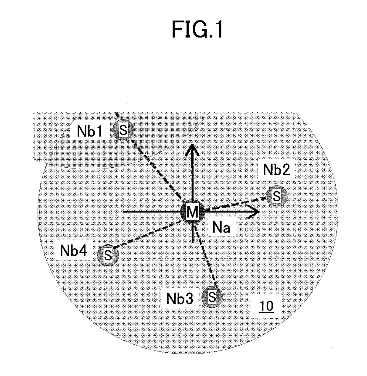
[0040]2. Application Scenario

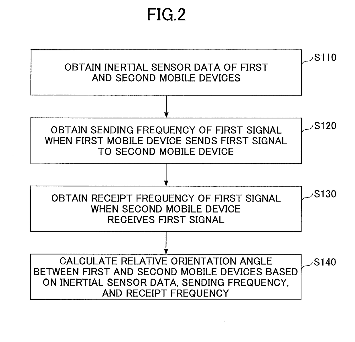
[0041]3. Relative Orientation Angle Calculation Method

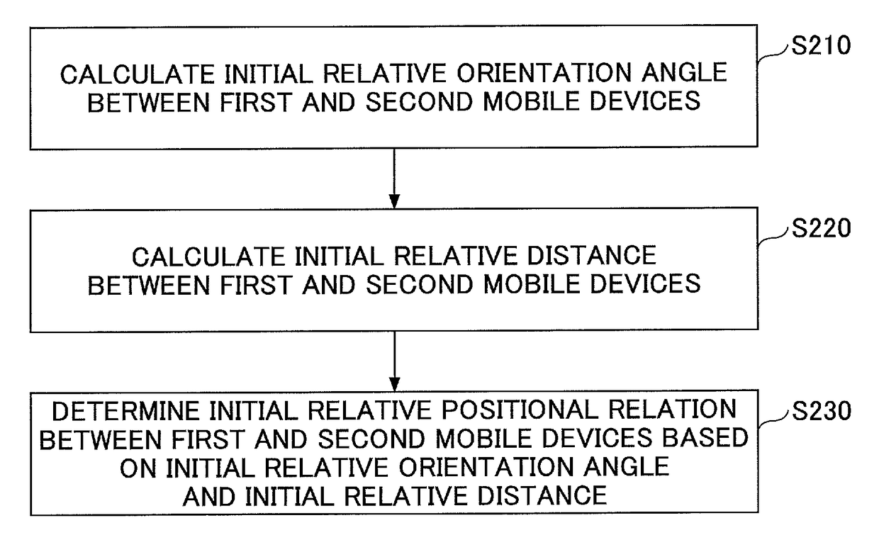
[0042]4. Relative Positioning Method of Mobile Device

[0043]5. Example of Relative Positioning Method of Mobile Device

[0044]6. Relative Orientation Angle Calculation Device

[0045]7. Relative Positioning Apparatus

[0046]8. Mobile Device

1. Outline of Thought of Invention

[0047]In the research for solving the technical problems existing in the conventional techniques, it has been found by the inventors that in most calculation processes of a relative orientation angle, the principle of the Doppler effect is adopted to compensate for the receipt frequency of a radio signal which is received by a mobile device on the receipt side (...


PUM


Abstract

Disclosed is a relative orientation angle calculation method comprising steps of obtaining inertial sensor data of first and second mobile devices, the first mobile device being capable of sending a first signal to the second mobile device; obtaining a sending frequency that the first signal has when the first mobile device sends the first signal to the second mobile device; obtaining a receipt frequency that the first signal has when the second mobile device receives the first signal sent from the first mobile device, the first signal receiving influence of the Doppler effect in a sending process in which the first signal is sent to the second mobile device from the first mobile device; and calculating, based on the inertial sensor data, the sending frequency, and the receipt frequency, a relative orientation angle between the first and second mobile devices.

Description

BACKGROUND OF THE INVENTION[0001]1. Field of the Invention[0002]The present invention relates to the field of wireless communications, and particularly relates to a method and device for calculating a relative orientation angle as well as a relative positioning method.[0003]2. Description of the Related Art[0004]In general, the relative orientation angle between two mobile devices (e.g., first and second mobile devices) refers to the angle between the device orientation of one of the two mobile devices and the straight-line direction along the straight line from the one mobile device to another.[0005]At present, in the conventional relative orientation angle calculation methods, first it is necessary to obtain the initial coordinates of the two mobile devices and their inertial sensor data on the basis of which the relative positions (coordinates) of the two mobile devices in a moving state are estimated, and then, the relative orientation angle between the two mobile devices may be...

Claims


Application Information

Patent Timeline
Patent Type & Authority Patents(United States)
IPC IPC(8): G01C21/16G01S5/02
CPCG01S5/0289G01C21/165
Inventor LIAO, KEDA, BINWANG, WEIYU, HAIHUAYI, HONG
Owner RICOH KK
Why Eureka
Try Eureka