Lift fan position lock mechanism

a technology of position lock and lift fan, which is applied in the direction of magnets, vertical landing/take-off aircraft, magnets, etc., can solve the problems of generating drag and/or other undesirable forces, and it is not practical to use conventional mechanisms to lock the lift fan rotor

Active Publication Date: 2017-10-10
WISK AERO LLC
View PDF9 Cites 29 Cited by
  • Summary
  • Abstract
  • Description
  • Claims
  • Application Information

AI Technical Summary

Benefits of technology

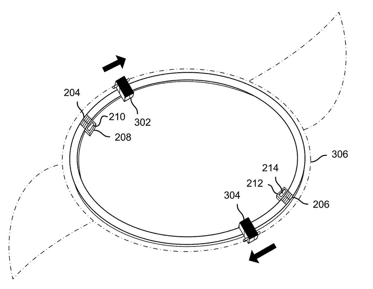
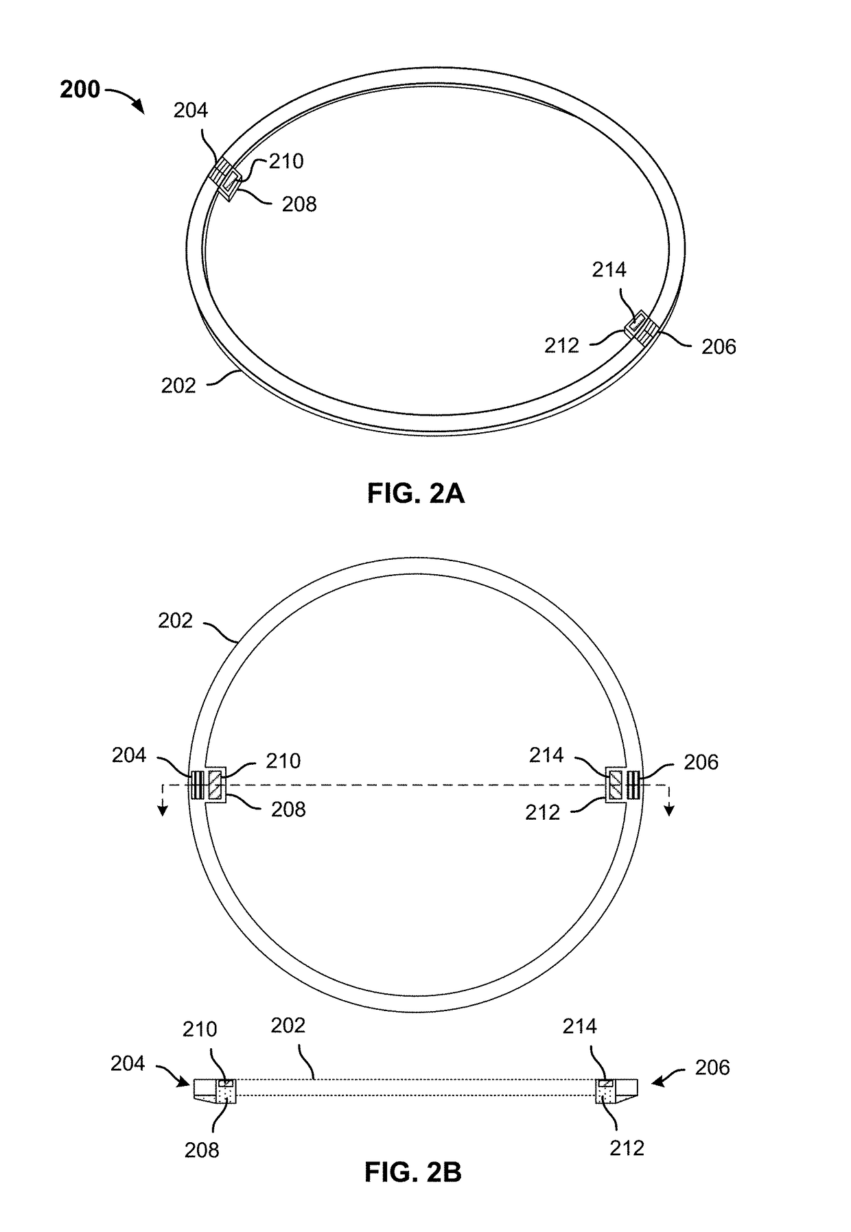
The invention is a mechanism for locking and unlocking lift fans in multi-rotor aircraft. The mechanism uses a rotor magnet and a stationary magnet to hold the lift fan rotor in place when the aircraft is in vertical flight mode. The mechanism can be used to transition from a locked to an unlocked state and vice versa. The technical effect of the invention is to provide a reliable and effective way to lock and unlock lift fans in multi-rotor aircraft, which can improve safety and reliability.

Problems solved by technology

In the forward flight mode, unless locked the lift fans may generate drag and / or other undesirable forces.
It may not be practical to use conventional mechanisms to lock lift fan rotors, e.g., due to weight considerations, uncertainty as to rotor position as the aircraft transitions into forward flight, and / or other considerations.

Method used


Image

  • Lift fan position lock mechanism
  • Lift fan position lock mechanism
  • Lift fan position lock mechanism

Examples


Embodiment Construction

[0017]The invention can be implemented in numerous ways, including as a process; an apparatus; a system; a composition of matter; a computer program product embodied on a computer readable storage medium; and / or a processor, such as a processor configured to execute instructions stored on and / or provided by a memory coupled to the processor. In this specification, these implementations, or any other form that the invention may take, may be referred to as techniques. In general, the order of the steps of disclosed processes may be altered within the scope of the invention. Unless stated otherwise, a component such as a processor or a memory described as being configured to perform a task may be implemented as a general component that is temporarily configured to perform the task at a given time or a specific component that is manufactured to perform the task. As used herein, the term ‘processor’ refers to one or more devices, circuits, and / or processing cores configured to process da...


PUM

PropertyMeasurementUnit
magnetic polarityaaaaaaaaaa
sizeaaaaaaaaaa
spring forceaaaaaaaaaa

Abstract

A lift fan position lock mechanism is disclosed. In various embodiments, a position lock mechanism includes a ring structure having a first surface, the ring structure including one or more detents defined in the first surface of the ring structure. For each detent, the lock mechanism includes a stationary magnet coupled fixedly to the ring structure at a location adjacent to the detent. The lock mechanism further includes a rotating magnet assembly comprising a magnet of opposite magnetic polarity to at least one of the stationary magnets and a mechanical stop structure of a size and shape to fit into a corresponding detent and engage mechanically with a surface defining at least one extent of said corresponding detent when the rotating magnet assembly is in a locked position.

Description

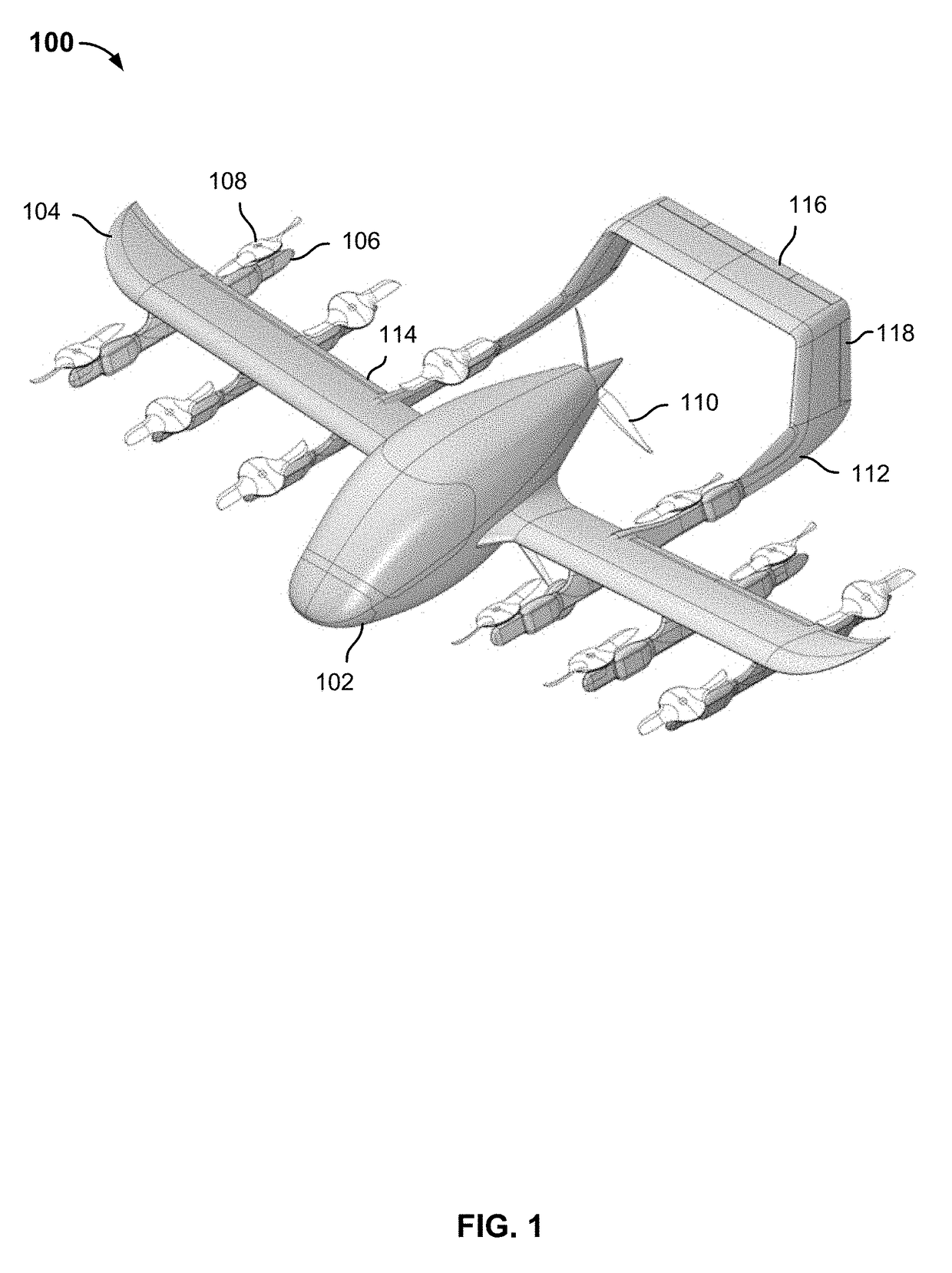
BACKGROUND OF THE INVENTION[0001]Lift fans and other rotors, collectively referred to herein as “lift fans”, may be used to provide lift to manned or unmanned multirotor aircraft, such as personal aircraft and drones. Mixed flight mode aircraft may use lift fans to provide lift in a vertical flight mode, e.g., to take off, hover, or land. Such an aircraft may transition after takeoff into a forward flight mode in which one or more forward flight propellers may be used to propel the aircraft through the air. Lift may be generated in the forward flight mode by one or more wings comprising the aircraft.[0002]In the forward flight mode, unless locked the lift fans may generate drag and / or other undesirable forces. It may not be practical to use conventional mechanisms to lock lift fan rotors, e.g., due to weight considerations, uncertainty as to rotor position as the aircraft transitions into forward flight, and / or other considerations.BRIEF DESCRIPTION OF THE DRAWINGS[0003]Various embo...

Claims


Application Information

Patent Timeline
Patent Type & Authority Patents(United States)
IPC IPC(8): B64C27/32H01F7/02B64C29/00
CPCB64C27/322H01F7/0226B64C29/0091B64C29/0025B64C27/24B64C27/30B64C27/48H01F7/0247H02K49/10B64C2027/8236B64C2027/8272B64C2027/8281B64C27/26
Inventor MOORE, ROBERT WAYNELONG, GEOFFREY ALAN
Owner WISK AERO LLC
Why Eureka
Try Eureka