Vessel insulation assembly

a technology of assembly and vehicle, applied in the direction of packaging goods, cosmonautic vehicles, food packaging, etc., can solve the problems of not meeting the strength and reusability requirements associated with multi-mission flight environments, the technology, and the inability to integrate expendable launch systems into reusable vehicle designs, etc., to achieve the effect of satisfying the strength and reusability requirements and reducing the operating costs of the vehicl

Active Publication Date: 2017-10-10
THE BOEING CO
View PDF44 Cites 69 Cited by
  • Summary
  • Abstract
  • Description
  • Claims
  • Application Information

AI Technical Summary

Problems solved by technology

The quantity of propellant required for most missions, especially for launch / takeoff requirements, often generates severe design constraints and can require considerable portions of vehicle size to be dedicated towards the carrying of propellant.
This technology, however, does not commonly satisfy the strength and reusability requirements associated with multi-mission flight environments.
Expendable launch systems are often not considered appropriate for integration into reusable vehicle designs, such as commercial aircraft and reusable space vehicles.
However, such foams are generally not suitable as cryoinsulation by themselves owing to their tendency to crack, delaminate from the propellant vessel walls, and / or fragment (a condition often referred to as spalling where flakes of a material detach from a larger solid body) when subjected to a combination of cryogenic temperatures and mechanical loads.
However, such honeycomb material substantially increases the weight of the reusable aerospace vehicle, which leads to additional propellant consumption and higher costs.

Method used


Image

  • Vessel insulation assembly
  • Vessel insulation assembly
  • Vessel insulation assembly

Examples


Embodiment Construction

[0023]The described embodiments relate to a cryofoam insulation assembly having a microtruss structure encased therein. In various embodiments, the truss structure includes a plurality of members extending from a node and attached to a support structure. In certain embodiments, the truss members are hollow. With regard to both hollow and non-hollow truss embodiments, a foam material is applied about the microtruss such that the microtruss provides a structural core of the cryofoam insulation.

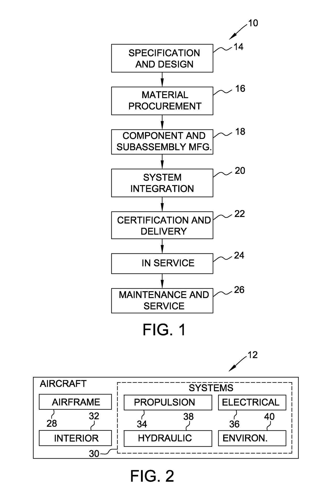
[0024]Referring FIG. 1, implementations of the disclosure may be described in the context of an aircraft manufacturing and service method 10 and via an aircraft 12 (shown in FIG. 2). During pre-production, including specification and design 14 data of aircraft 12 may be used during the manufacturing process and other materials associated with the airframe may be procured 16. During production, component and subassembly manufacturing 18 and system integration 20 of aircraft 12 occurs, prior to ai...


PUM

PropertyMeasurementUnit
diameteraaaaaaaaaa
diameteraaaaaaaaaa
densityaaaaaaaaaa

Abstract

A vessel includes a vessel wall and an insulation assembly coupled to the vessel wall. The insulation assembly includes a stochastic foam material and a microtruss structure encased within the foam material. The microtruss structure includes a plurality of truss members interconnected at a plurality of nodes. Each truss member is in contact with the foam material such that the microtruss structure provides a structural core for the foam material.

Description

CROSS REFERENCE TO RELATED APPLICATIONS[0001]This application claims priority to U.S. Provisional Application No. 62 / 042,232 filed on Aug. 26, 2014, which is hereby incorporated by reference in its entirety.BACKGROUND[0002]The present disclosure relates generally to an insulation assembly for use with cryogenic propellant vessels, and, more specifically, to an insulation assembly that includes a micro-truss reinforced cryofoam.[0003]Aerospace vehicle designs commonly utilize a variety of propellants to supply both launch / takeoff and maneuvering power requirements. The quantity of propellant required for most missions, especially for launch / takeoff requirements, often generates severe design constraints and can require considerable portions of vehicle size to be dedicated towards the carrying of propellant. The use of cryogenic propellants allows the propellants to be maintained in a liquid state rather than in their room temperature gaseous form. This allows a greater quantity of pr...

Claims


Application Information

Patent Timeline
Patent Type & Authority Patents(United States)
IPC IPC(8): B29C44/18B32B15/08B32B3/28B32B3/26B32B3/18B32B3/12B32B3/08B32B27/12B32B27/08B32B27/06B32B15/14B32B15/04B32B9/04B32B9/00B32B7/12B32B5/26B32B5/24B32B5/22B32B5/20B64G1/40B32B5/02B29K25/00B29K27/06B29K75/00B29K79/00B29K105/04B29L31/30
CPCB64G1/402B29C44/18B32B3/08B32B3/12B32B3/18B32B3/266B32B3/28B32B5/02B32B5/028B32B5/20B32B5/22B32B5/245B32B5/26B32B7/12B32B9/005B32B9/045B32B9/046B32B9/047B32B15/046B32B15/08B32B15/14B32B27/065B32B27/08B32B27/12B32B2307/726B32B2307/724B32B2605/18B29K2025/06B29K2027/06B29K2075/00B29K2079/08B29K2105/04B29L2031/3097B32B2255/02B32B2255/06B32B2255/102B32B2255/26B32B2260/021B32B2260/046B32B2262/02B32B2262/103B32B2262/105B32B2262/106B32B2266/0214B32B2266/0228B32B2266/0235B32B2266/0278B32B2266/06B32B2266/08B32B2305/022B32B2307/304B32B2307/718B32B2439/40
Inventor EMBLER, JONATHAN D.GAYNOR, III, TIMOTHY LEOROPER, CHRISTOPHER S.SCHAEDLER, TOBIAS A.FUKUSHIMA, JEFFREY DALEHAND, MICHAEL LESLIECHONG, KEITH Y.SCHUBERT, RANDALL COLIN
Owner THE BOEING CO
Why Eureka
Try Eureka