Spray booth spray racks

a spray booth and spray rack technology, applied in the direction of coatings, cabinets, manufacturing tools, etc., can solve the problems of large amount of bulky equipment, affecting the operation posing significant health hazards and environmental hazards, so as to reduce the operating cost of the paint booth, reduce environmental contamination, and reduce health risks for employees

Inactive Publication Date: 2017-10-17
PHILLIPPI PATRICK G
View PDF12 Cites 0 Cited by
  • Summary
  • Abstract
  • Description
  • Claims
  • Application Information

AI Technical Summary

Benefits of technology

[0015]Furthermore, the majority of modern industrial painting utilizes paint shops and booth structures that have been devised to effectively employ various air flow design characteristics, to reduce paint booth operating costs while minimizing environmental contamination. Modern paint booths of this design are known as downdraft paint booths and are equipped with a grate replacing much of the flooring. This grate allows excess aerosolized paint that misses a part to be sucked downwards and filtered, drastically reducing health risks to the employees of the paint shop, and drastically reducing the environmental hazards posed by paint circulating into the air. However, such grates pose significant downsides to the traditional paint stands described above. First, they prevent the wheeled stands from moving effectively traversing the floor of a paint ship, and second they often cause instability of a paint stand. Therefore, a paint stand that is capable of removably securing itself to a floor grate is contemplated by the present invention.

Problems solved by technology

Painting car, motorcycle, and other automotive parts is a difficult process that poses significant health hazards as well as hazards to the environment.
In addition, the process of painting these parts can require a large amount of bulky equipment which needs to be moved and stored wasting valuable floor space for the painter and his workshop.
These traditional stands are typically difficult to move, or are equipped with wheels which are unreliable, and also can cause issues during the painting process.
However, such grates pose significant downsides to the traditional paint stands described above.
First, they prevent the wheeled stands from moving effectively traversing the floor of a paint ship, and second they often cause instability of a paint stand.

Method used


Image

  • Spray booth spray racks
  • Spray booth spray racks
  • Spray booth spray racks

Examples


Embodiment Construction

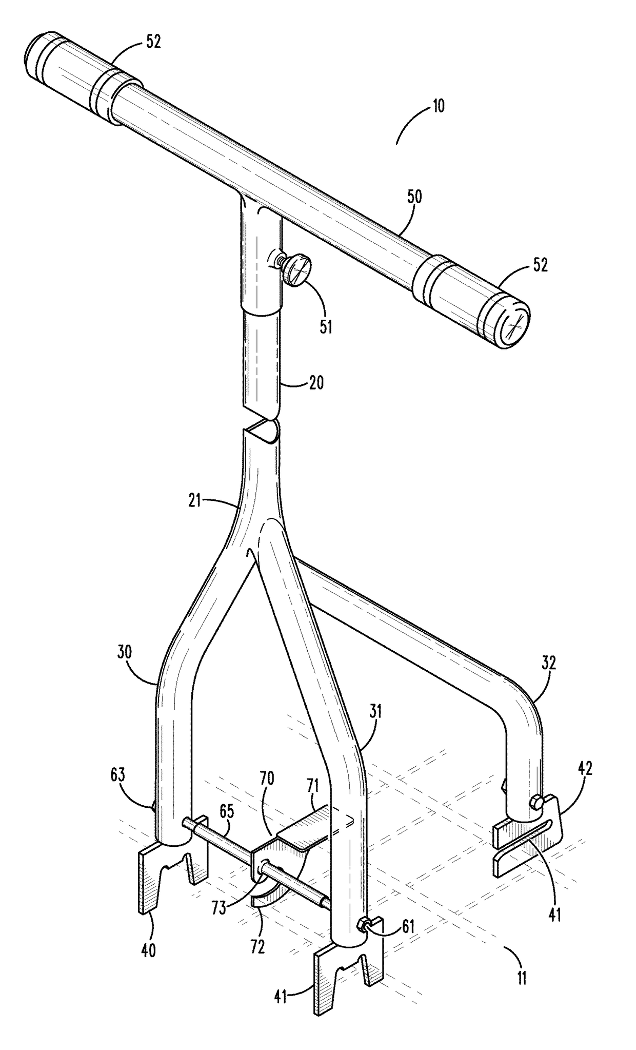
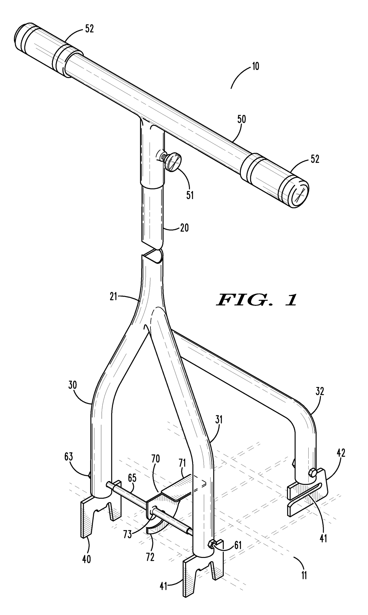
[0034]Referring now the drawings with more specificity, the present invention essentially provides an improved paint stand or paint rack that is particularly effective at coupling with a grate, typically a floor grate used in modern downdraft paint booths. Such coupling provides for stability while minimizing floor footprint.

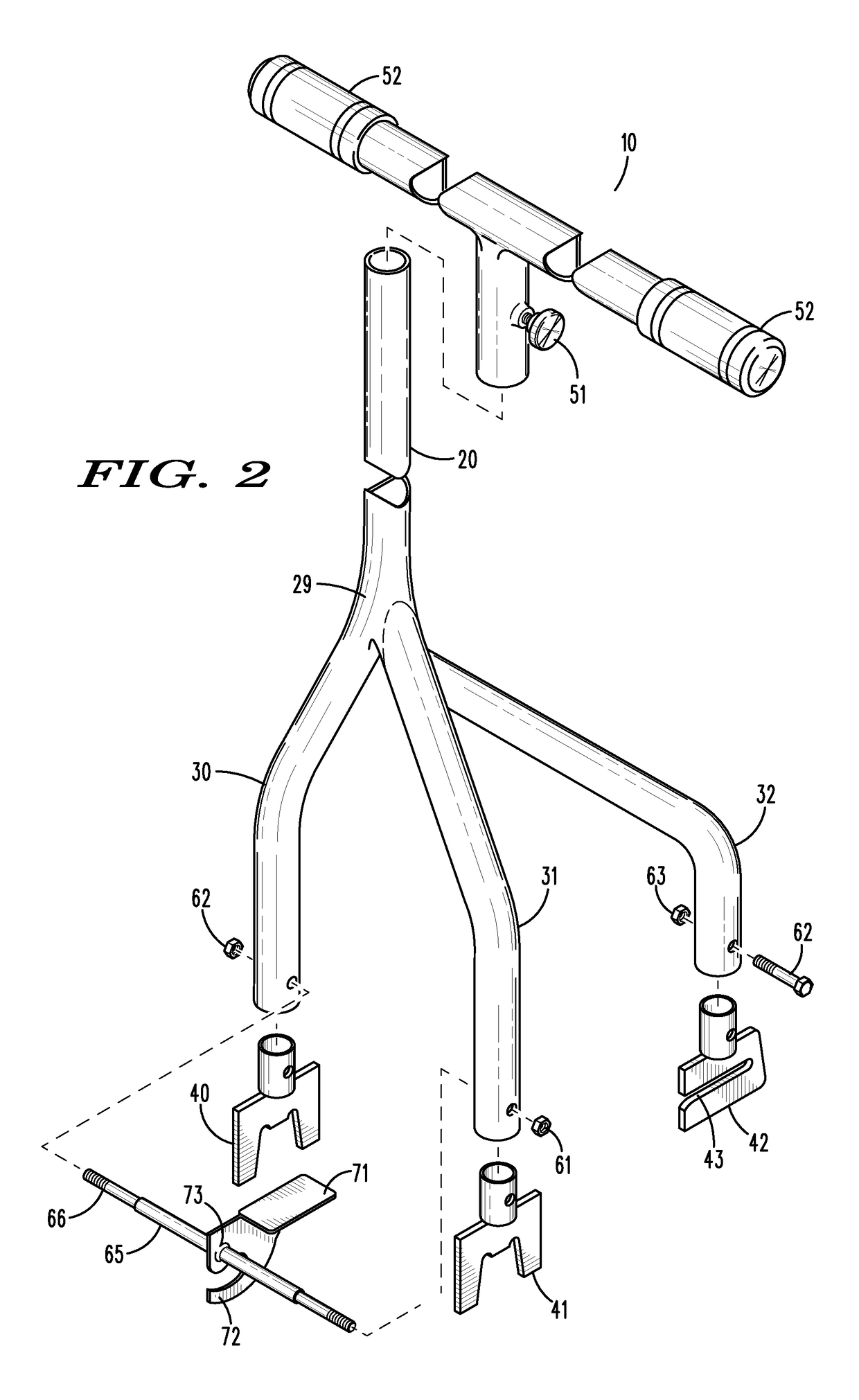
[0035]Looking now to FIG. 1, paint rack 10 is a preferred embodiment of a paint rack which may preferably be coupled to industrial grate 11. Paint rack 10 may preferably be fabricated out of steel, stainless steel, aluminum, and / or other analogous metallic alloys and may be comprised of solid bars or hollow tubes to increase strength or decrease weight depending on the needs of the user. Paint rack 10 according to the present invention, preferably comprises, an attachment support bar 20, three leg portions 30, 31, 32, and three grate attachment portions 40, 41, 42, and paint stand 50.

[0036]The attachment support bar 20 preferably comprises the main body of paint...


PUM

PropertyMeasurementUnit
lengthaaaaaaaaaa
lengthaaaaaaaaaa
depthaaaaaaaaaa

Abstract

A paint rack having an attachment support bar, three leg portions, and three grate attachment portions, the three grate attachment portions matably attachable to a floor grate, the three leg portions mounted on top of the three grate attachment portions and extending upwardly from the grate attachment portions, the attachment support bar connected to the three leg portions, and extending upwardly from the three leg portions.

Description

BACKGROUND OF THE INVENTION[0001]Field of the Invention[0002]The present invention generally relates to a spray booth, spray rack, and painting assembly and related methods. More particularly, the present invention relates to an adaptable paint rack which can be adjusted to be cooperable with various paint racks, and floor mechanisms.[0003]Discussion of the Prior Art[0004]U.S. Pat. No. 3,858,864 ('864 Patent), which issued to Waldo, discloses a Vehicle Door Supporting Apparatus. The '864 Patent describes a door supporting apparatus for supporting a door of a vehicle in a desired position comprises a movable dolly base. An angular member is rotatably mounted on the base in a manner whereby it is at substantially right angles to the base in one position and substantially parallel to the base in another position.[0005]U.S. Pat. No. 4,530,492 ('492 Patent), which issued to Bork, discloses an Apparatus for Supporting Vehicle Body Parts. The '492 Patent describes an apparatus and method f...

Claims


Application Information

Patent Timeline
Patent Type & Authority Patents(United States)
IPC IPC(8): B23P11/00A47B81/00B05B15/12
CPCB05B15/1203A47B81/00B05B15/1214B05B13/0285B05B15/80B05B16/40
Inventor PHILLIPPI, PATRICK G.
Owner PHILLIPPI PATRICK G
Why Eureka
Try Eureka