System and method for environmental adaptation of display characteristics

a display characteristic and environmental adaptation technology, applied in the field of display, can solve the problems of difficulty in a display to match the dynamic range of luminance that exists in the real world, and inability to achieve true three-dimensional depth reproduction

Inactive Publication Date: 2017-10-24
MFG RESOURCES INT INC
View PDF268 Cites 17 Cited by
  • Summary
  • Abstract
  • Description
  • Claims
  • Application Information

AI Technical Summary

Problems solved by technology

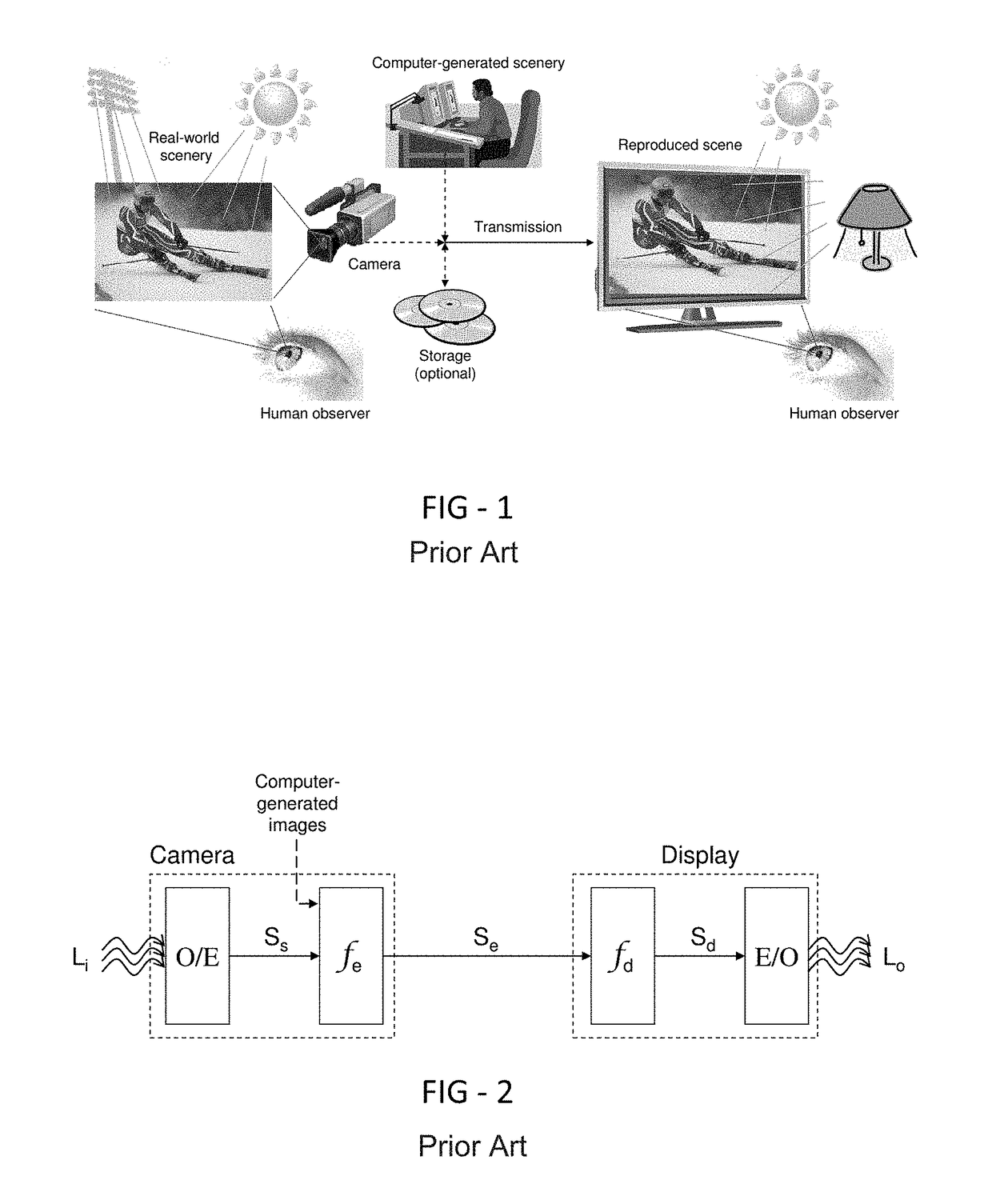
One of the major impediments to high-fidelity reproduction is that the local viewing environment of the final observer cannot be definitively predicted, yet the viewing environment can have a profound impact on the visual quality of the reproduction.
But there are several inherent and unavoidable limitations.
One such limitation is the difficulty for a display to match the dynamic range of luminance that exists in the real world, especially at the upper end of the scale (e.g., the sun and reflections thereof).
Another limitation is that a display is a predominately “flat” version of the original scene; hence true three-dimensional (3D) depth reproduction is not possible, although various “3D” technologies exist to produce the illusion of depth, at least from one or more specific perspectives.
Also, common displays cannot begin to simulate the nearly hemispherical field-of-view of the human eye, although special venues such as IMAX® theaters attempt to overcome this.
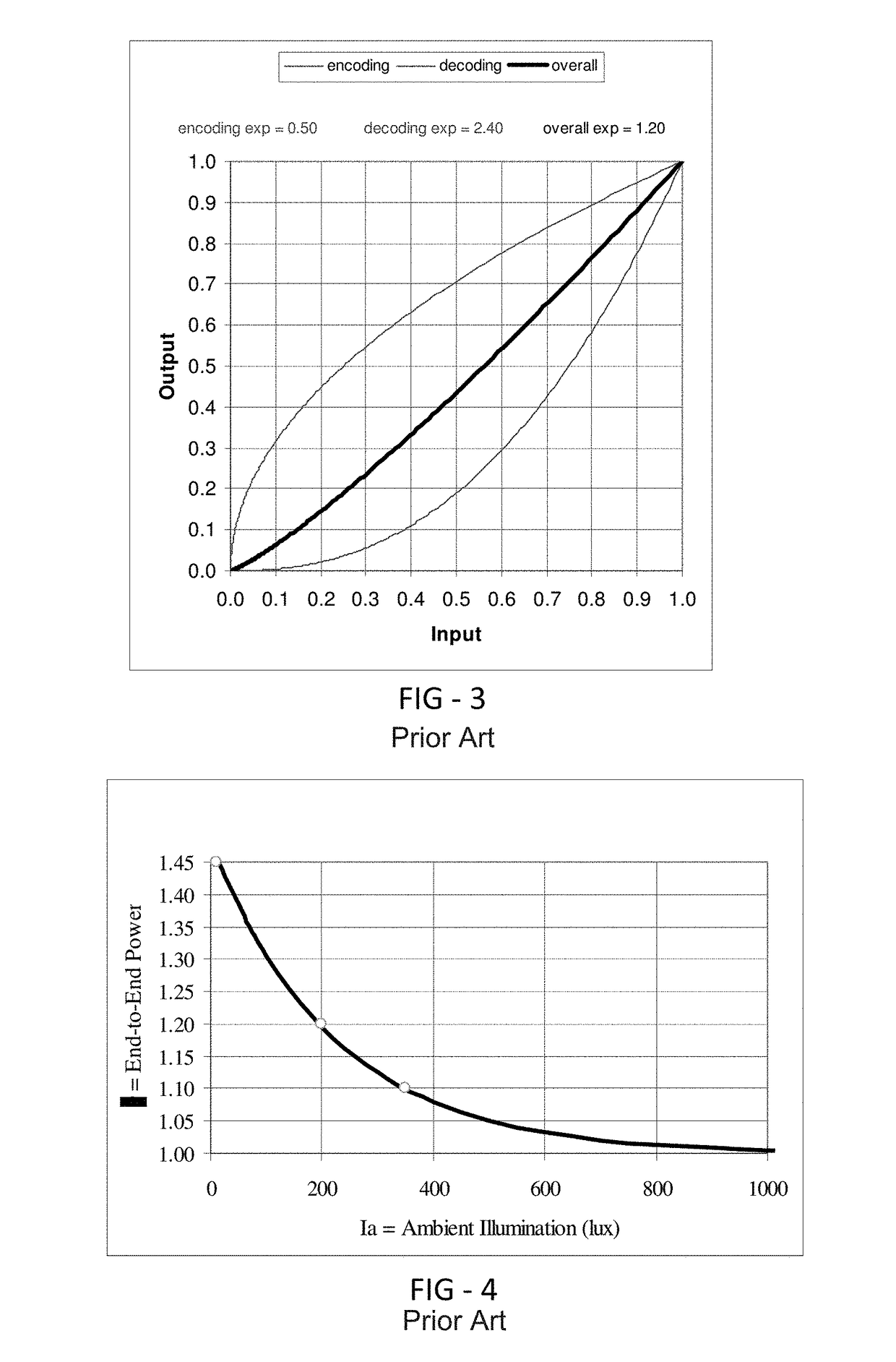
The primary reason for deviating from pure linearity is that a camera / display cannot practically reproduce the full dynamic range of light that exists in the real world.
However, few if any displays actually implement a power of ε≈1.

Method used


Image

  • System and method for environmental adaptation of display characteristics
  • System and method for environmental adaptation of display characteristics
  • System and method for environmental adaptation of display characteristics

Examples


exemplary embodiment 1

[0080

[0081]Referring to FIG. 11 the encoded image signal Se and environmentally-reactive control signal Sa are fed into the image signal processing block labeled ƒp which, in an exemplary embodiment, produces a pre-decoding image signal Sp according to Eq(5) below. This equation assumes that the all three image signal transformations (encoding, pre-decoder processing, and decoding) are performed with power law functions, although this is not a necessity for the invention. Eq(5) represents the processing functionality of block ƒp, accepting the input signals Sa and Se and outputting the signal Sp. A new feature of this embodiment is the introduction of a gray level threshold labeled St, leading to the two conditional cases expressed in Eq(5). The 1st condition is applicable when encoded signal levels fall below a level that is derived from St, in which case those signal levels will be set to 0 (i.e., full black). Otherwise, the 2nd condition in Eq(5) is applicable for encoded signal ...

exemplary embodiment 2

[0091

[0092]The “cliff” type of threshold cutoff produced by Eq(5) and illustrated in FIG. 13 may produce objectionable visual artifacts in the image, especially for higher levels of thresholds and / or black level offsets. This would manifest as darker regions in an image that suddenly and unnaturally become black—this a phenomena that is sometimes referred to as banding. This effect can be reduced by softening the edge of the threshold.

[0093]Referring back to FIG. 11 the encoded image signal Se and environmentally-reactive control signal Sa are fed into the image signal processing block labeled ƒp which, in an exemplary embodiment, produces a pre-decoding image signal Sp according to Eq(6) below. This equation assumes that the all three image signal transformations (encoding, pre-decoder processing, and decoding) are performed with power law functions, although this is not a necessity for the invention. Eq(6) represents the processing functionality of block ƒp, accepting the input si...

exemplary embodiment 3

[0104

[0105]The linear ramp provided as a transition between full off and threshold in the previous embodiment affords a significant reduction in visual artifacts, or banding, but there is still a sharp point in the end-to-end transform curve shown in FIG. 14 that has the potential to produce visual artifacts. To further improve the transition, a specific example using a sine curve will be described below, although other functions could be used.

[0106]Referring back to FIG. 11 the encoded image signal Se and environmentally-reactive control signal Sa are fed into the image signal processing block labeled ƒp which, in an exemplary embodiment, produces a pre-decoding image signal Sp according to Eq(7) below. This equation assumes that the all three image signal transformations (encoding, pre-decoder processing, and decoding) are performed with power law functions, although this is not a necessity for the invention. Eq(7) represents the processing functionality of block ƒp, accepting the...


PUM


Abstract

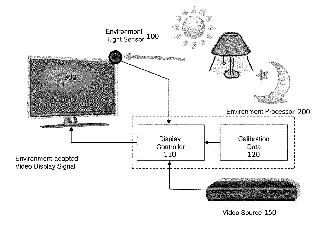
A system and method for altering the characteristics of a display based on environmental data is disclosed. Exemplary embodiments provide a light sensor, an environmental processing unit which is adapted to receive electrical signals from the light sensor and generate an environmentally-reactive control signal (Sa), an image signal processor which accepts Sa and an encoded image signal (Se) and generates a pre-decoding image signal (Sp), and an image signal decoder which accepts Sp and generates a decoded image signal for the display. The environmentally-reactive control signal (Sa) may contain the instantaneous value of the desired display black level Sb. Alternatively or additionally, the environmentally-reactive control signal (Sa) may contain a signal linearity modification value.

Description

CROSS-REFERENCE TO RELATED APPLICATIONS[0001]This application claims priority to U.S. Application No. 61 / 538,319 filed on Sep. 23, 2011 and U.S. Application No. 61 / 653,201 filed on May 30, 2012, both of which are hereby incorporated by reference in their entirety.TECHNICAL FIELD[0002]The exemplary embodiments herein pertain to a display and a method that utilizes measured properties of the viewing environment in order to automatically vary the visual characteristics of a display according to a set of predefined rules. Some embodiments provide an autonomous display that exhibits optimal visual perception for image reproduction at all environmental viewing conditions.BACKGROUND OF THE ART[0003]Displays are used in a very wide range of applications, including entertainment (e.g., television, e-books), advertisement (e.g., shopping malls, airports, billboards), information (e.g., automotive, avionics, system monitoring, security), and cross-applications (e.g., computers, smart phones)—t...

Claims


Application Information

Patent Timeline
Patent Type & Authority Patents(United States)
IPC IPC(8): G09G5/10H04N21/422H04N5/58G09G5/02H04N21/431
CPCG09G5/10G09G5/02H04N5/58H04N21/42202H04N21/4318G09G2360/144G09G2320/0271G09G2320/066G09G2320/0626G09G2320/0646G09G2320/0238
Inventor DUNN, WILLIAMPRESLEY, HARRYWASINGER, JERRY
Owner MFG RESOURCES INT INC
Why Eureka
Try Eureka