
Bracket device

a bracket and bracket technology, applied in the field of bracket devices, can solve problems such as errors in installation or even endanger the operator and the equipment in question

Active Publication Date: 2017-10-31
KING SLIDE WORKS CO LTD +1
View PDF12 Cites 16 Cited by
  • Summary
  • Abstract
  • Description
  • Claims
  • Application Information

AI Technical Summary

Benefits of technology

The patent describes a bracket device that can be mounted on a slide rail and attached to a post. The bracket has a side plate and an end plate, with mounting members attached to the end plate. The bracket is locked to the post using a locking member. The locking member can be blocked from moving to an unlocked position by a fool-proofing member, preventing the mounting members from being mounted on the post. The locking member has a position-limiting portion that presses against the side plate of the bracket when in the locked position. The bracket device includes an elastic member to keep the locking member in position.

Problems solved by technology

Nevertheless, a marked slide rail or bracket may still be mounted on the wrong side of a rack due to the operator's negligence, resulting in an error in installation or even endangering the operator and the equipment in question.

Method used


Image

  • Bracket device
  • Bracket device
  • Bracket device

Examples


Embodiment Construction

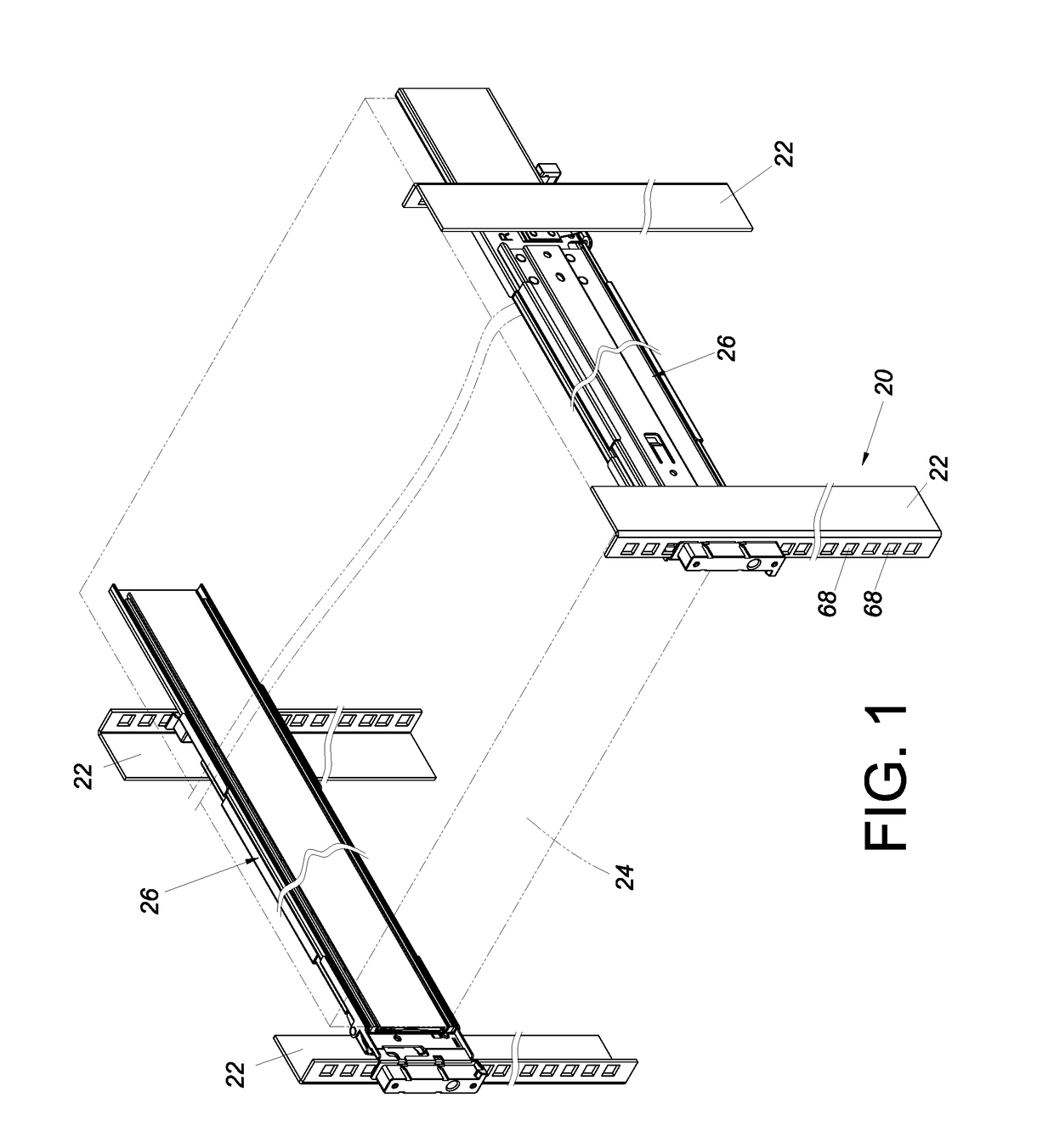
[0020]Referring to FIG. 1, a rack 20 includes a plurality of posts 22 arranged in bilateral symmetry. An object, such as a chassis 24, is mounted on the left and right posts 22 of the rack 20 via a pair of slide rail assemblies 26 respectively and is thus mounted on the rack 20.

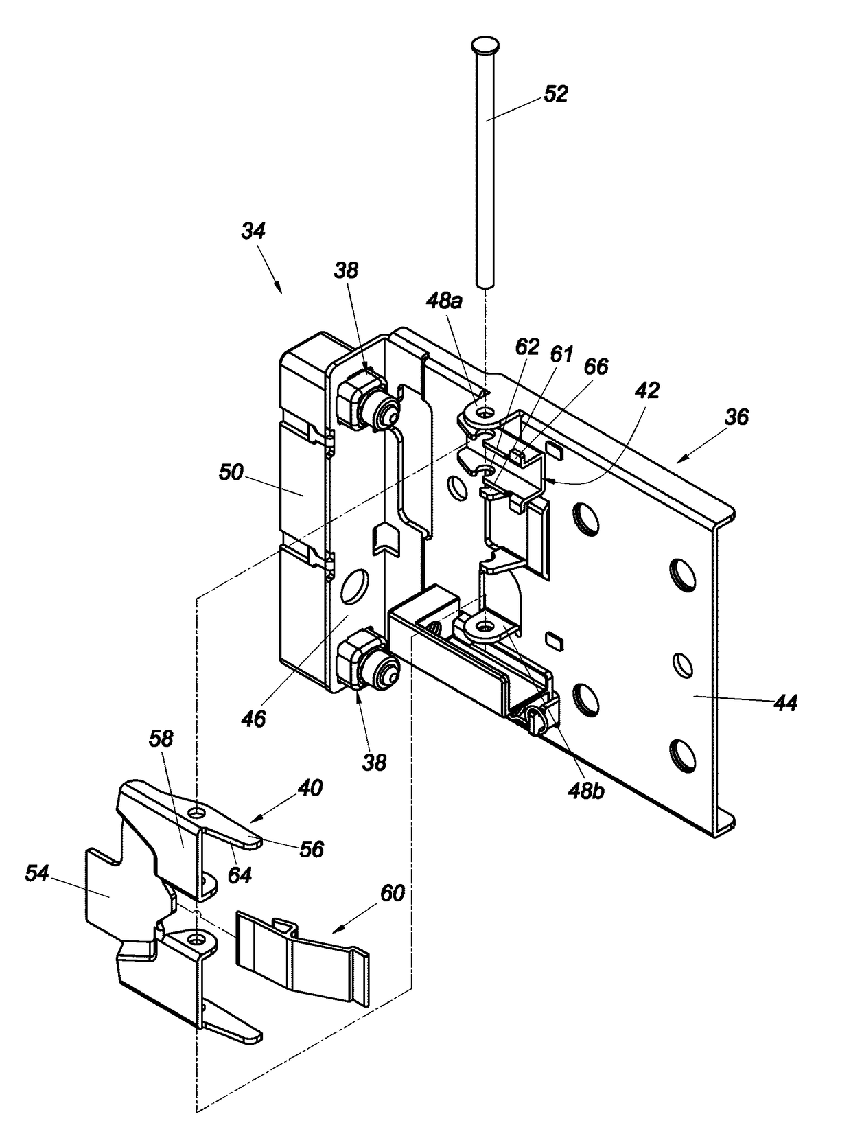
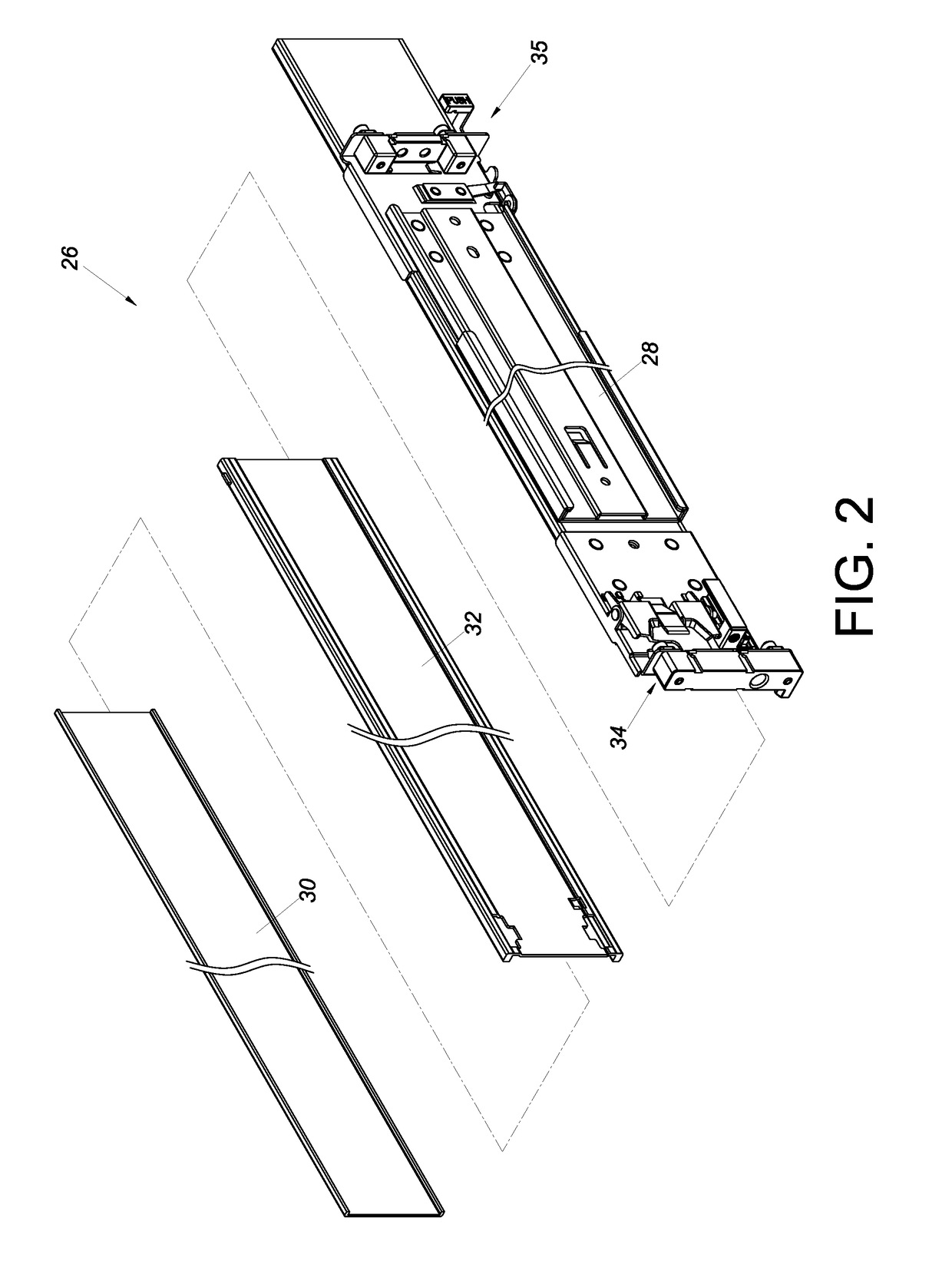
[0021]As shown in FIG. 2, the slide rail assembly 26 in an embodiment of the present invention includes a first rail 28, a second rail 30, and a third rail 32 movably provided between the first rail 28 and the second rail 30. The third rail 32 serves to increase the distance by which the second rail 30 can be extended with respect to the first rail 28. The first rail 28 has two portions, such as a front end portion and a rear end portion, which can be mounted with a first bracket device 34 and a second bracket device 35 respectively. The slide rail assembly 26 is mounted to the rack 20 via the two bracket devices 34 and 35. To illustrate the features of the present invention clearly, the following paragraphs ...


PUM


Abstract

A bracket device includes a bracket, at least one mounting member mounted on the bracket, a locking member movable with respect to the bracket, and a fool-proofing member to be located at a first position or a second position with respect to the bracket. When the bracket is at a first mounting angle, the fool-proofing member is located at the first position and is unable to block the locking member from moving with respect to the bracket. When the bracket is flipped from the first mounting angle to a second mounting angle, the fool-proofing member is displaced from the first position to the second position and ends up blocking the moving path of the locking member with respect to the bracket.

Description

FIELD OF THE INVENTION[0001]The present invention relates to a bracket device and more particularly to one with a fool-proofing function.BACKGROUND OF THE INVENTION[0002]U.S. Pat. No. 7,281,694 B2, granted to Allen et al., discloses a rack, or more specifically an equipment rack, including a plurality of posts, or vertical support columns (104), arranged in a bilaterally symmetric manner. An object, or rack-mount module (102), is mounted on the left and right vertical support columns (104) of the equipment rack via the mounting brackets (114) on a pair of slide rail assemblies and is thus mounted on the equipment rack. More specifically, in the embodiment shown in FIG. 4A to FIG. 4C of the specification of the afore-cited patent, a mounting bracket (200) has a base member (202) with a cantilevered flat spring (214). While the base member (202) of the mounting bracket (200) is being mounted to a vertical support column (104), the cantilevered flat spring (214) abuts against an end po...

Claims


Application Information

Patent Timeline
Patent Type & Authority Patents(United States)
IPC IPC(8): A47B96/06H05K7/14
CPCH05K7/1489A47B88/43
Inventor CHEN, KEN-CHINGYANG, SHUN-HOHO, CHUN-YIWANG, CHUN-CHIANG
Owner KING SLIDE WORKS CO LTD
Learn More