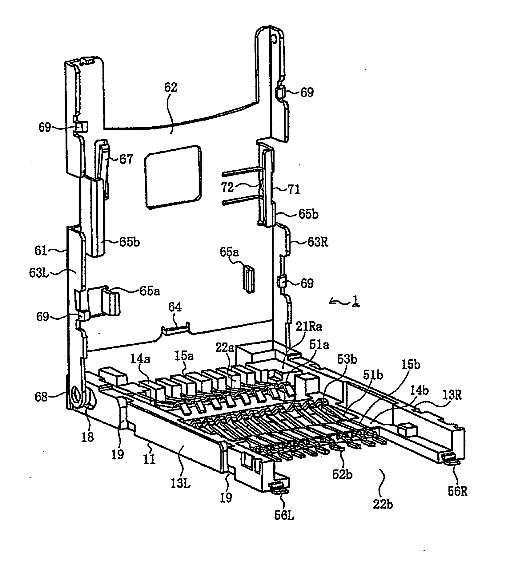
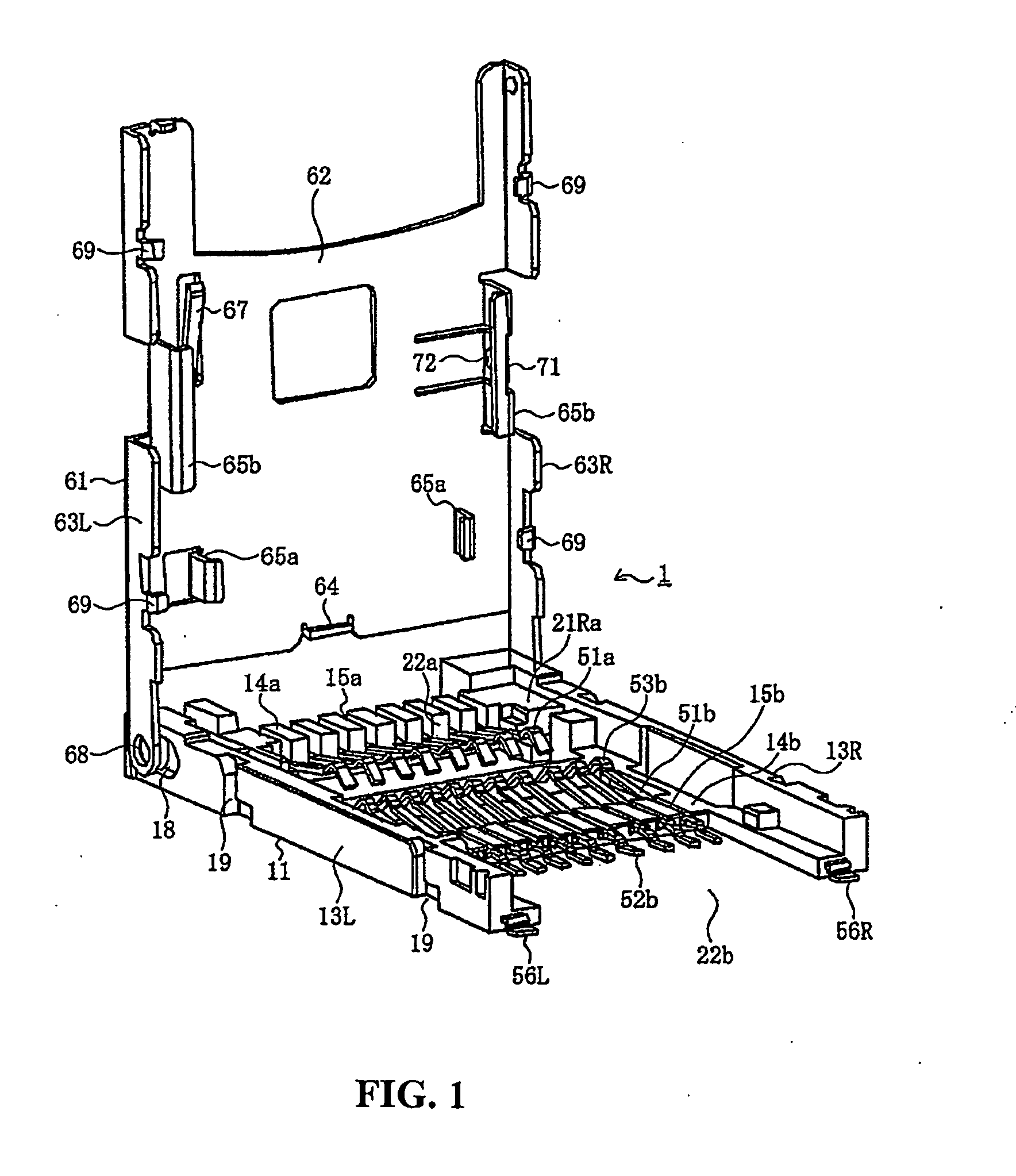
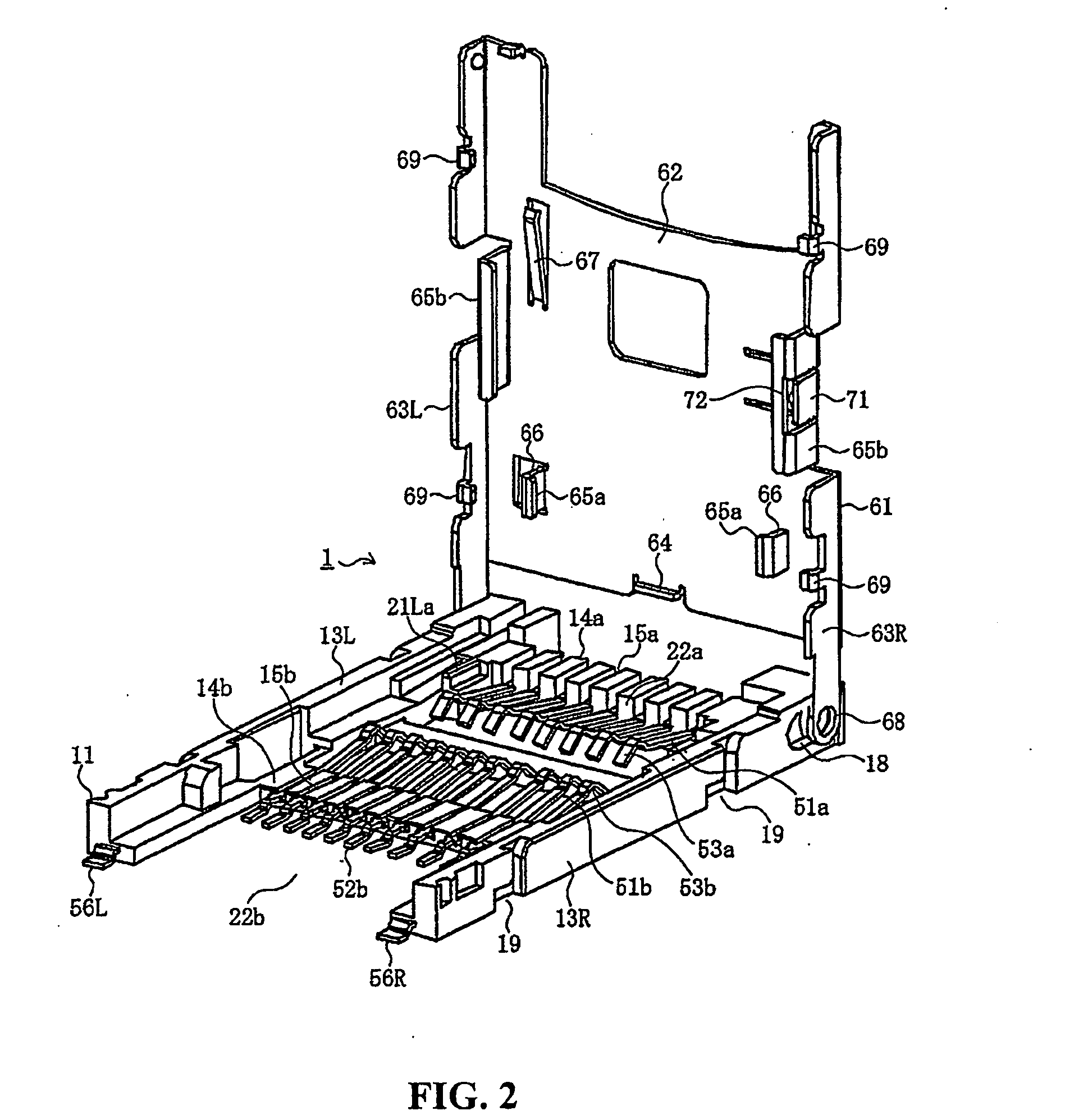
Card connector for receiving multiple cards

a card connector and card technology, applied in the direction of coupling device connection, coupling/disconnecting parts, instruments, etc., can solve the problems of increasing the overall size of the connector and the difficulty of attaching the connector to a small electronic devi

Inactive Publication Date: 2011-01-13
MOLEX INC
View PDF3 Cites 11 Cited by
  • Summary
  • Abstract
  • Description
  • Claims
  • Application Information

AI Technical Summary

Benefits of technology

[0010]It is an object of the invention to solve the problems encountered by the conventional card connector, and to provide a card connector which allows a positioning member provided for a cover member to discriminate a type of a card, so that the card connector can be small in its size with a minute thickness dimension, and that discrimination of a plurality of types of cards can be surely achieved, while unexceptionally avoiding mounting of a card on a wrong position or at a wrong attitude and ensuring that each of the plurality of types of cards is exclusively mounted in position.

Problems solved by technology

Nevertheless, in the conventional card connector described above, since the first card 901 and the second card 902 having different sizes, shapes, and so forth, are superimposed on each other and mounted, dimensions of the housing 811 and the holder portion 861 in a thickness direction must become lager, which in turn increases the overall size of the connector and makes it difficult to attach the connector to a small-sized electronic device.

Method used


Image

  • Card connector for receiving multiple cards
  • Card connector for receiving multiple cards
  • Card connector for receiving multiple cards

Examples


second embodiment

[0105]Next, a description of the present invention will be provided hereinbelow.

[0106]The members having like or identical structures as those in the first embodiment will be designated by the same reference numerals and descriptions thereof will be omitted. Descriptions of the same operations and effects as those in the first embodiment will also be omitted.

first embodiment

[0107]The present embodiment is described as another example of a card connector 1, which allows any one of “n” types of cards to be exclusively mounted therein, and “n” is 4 (four) in this case. This means, in the card connector 1 according to this embodiment, any one of the first card 101a, the second card 101b, and additional two types of cards, in other words, a third card 101c as a third type of card and a fourth card 101d as a fourth type of card can be exclusively mounted. The first card 101a to the fourth card 101d may be any types of cards, but the present embodiment is described as a case where the first card 101a and the second card 101b are a micro SD® card and a memory stick micro®, respectively, like the first embodiment, and the third card 101c is a mini SD® card, and the fourth card 101d is a SD® card.

[0108]In this embodiment, the first card 101a has the smallest width, the second card 101 b has a larger width than the first card 101a, the third card 101c has a large...

third embodiment

[0134]In the third embodiment, first card side face holding projection 65a through fourth card side face holding projections 65d on either the left or right side of shell 61 are arrayed along a straight line extending in the front and rear direction of a shell 61. In the illustrated example, the card side face holding projections on the right side are arrayed along the straight line adjacent the right side edge of the shell 61. The end positioning projection 64 is provided at a position corresponding to a position located between the paired first card side face holding projections 65a.

[0135]Comparing FIGS. 25-28 to FIGS. 19-22, it can be seen that the cards are retained in an identical manner in the third embodiment compared to the second embodiment but with the cards aligned adjacent the right side of shell 61 in the third embodiment. More specifically, the first card 101a is retained between first card side holding projections 65a and insertion is stopped by end positioning proje...


PUM


Abstract

A card connector is adapted to receive first and second electronic cards, each having a plurality of contact pads. The second card being wider than the first card. The connector includes an insulative housing with a plurality of first and second terminals mounted therein for engaging respective ones of the contact pads of the electronic cards when the cards are inserted into the connector. A cover member is pivotally mounted on the housing to permit movement of the cover member between an open position at which one of said first and second electronic cards may be inserted and a closed position at which the electronic card inserted into the cover is operatively positioned within the connector. The cover member has first and second sets of positioning members configured to position and hold electronic cards exclusively at the desired location for such card and wherein some of the positioning members of the first set also act as positioning members of the second set.

Description

BACKGROUND OF THE INVENTION[0001]The present invention relates generally to a card connector and more specifically to a card connector that may receive any of multiple sized cards.[0002]Conventionally, an electronic device such as a personal computer, a cellular phone, a PDA (personal digital assistant), a digital camera, a video camera, a music player, a game machine, a vehicle navigation device, and so on is provided with a card connector because of the fact that such an electronic device uses various types of memory cards such as a SIM (subscriber identity module) card, a MMC®(Multiple Media Card), a SD® (Secure Digital) card, a mini SD® card, Memory Stick®, Smart Media®, and so forth.[0003]In recent years, as the types of electronic devices have been diversified, memory cards are also showing a tendency of diversification. Therefore, a card connector in which not only one but two different types of memory cards can be mounted is proposed (For example, see Japanese Patent Applica...

Claims


Application Information

Patent Timeline
Patent Type & Authority Applications(United States)
IPC IPC(8): H01R13/62
CPCG06K13/0862H01R12/83H01R27/00H01R13/24
Inventor MATSUMOTO, YASUYOSHITOMITA, MITSUHIROMATSUKAWA, JUNNAITO, YUJI
Owner MOLEX INC
Why Eureka
Try Eureka