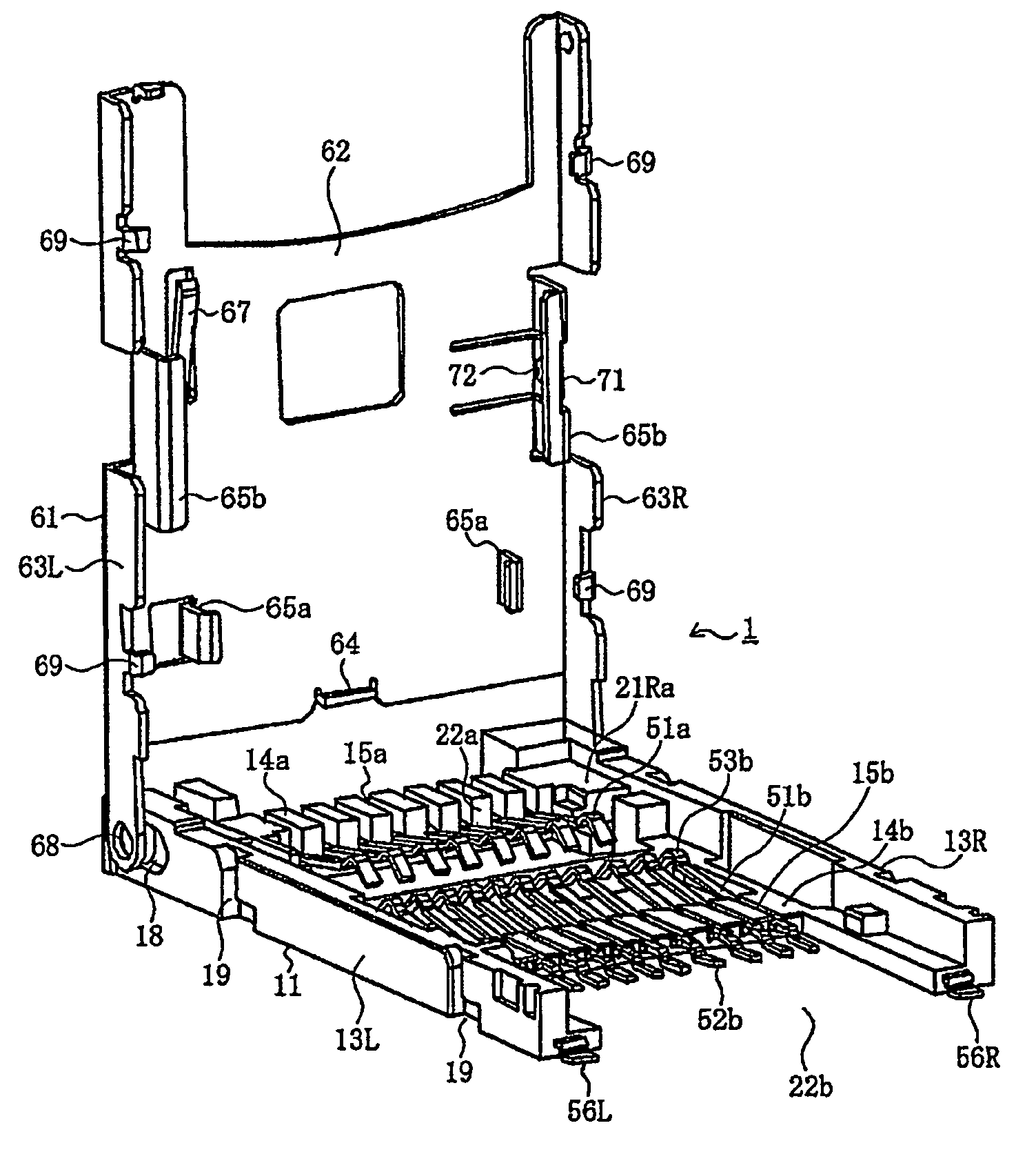
Card connector for receiving multiple cards
a card connector and card technology, applied in the direction of coupling device connection, coupling/disconnecting parts, instruments, etc., can solve the problems of increasing the overall size of the connector and the difficulty of attaching the connector to a small electronic devi
- Summary
- Abstract
- Description
- Claims
- Application Information
AI Technical Summary
Benefits of technology
Problems solved by technology
Method used
Image
Examples
first embodiment
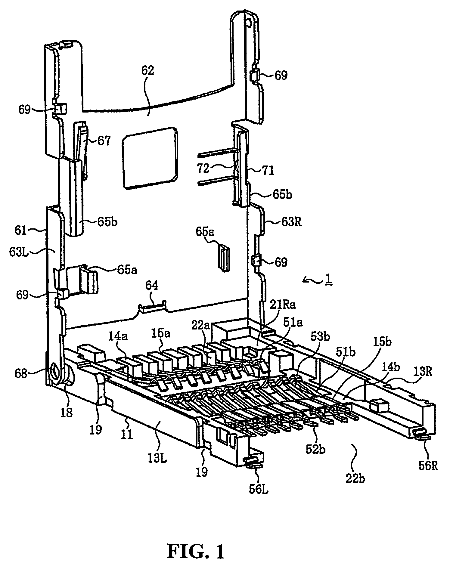
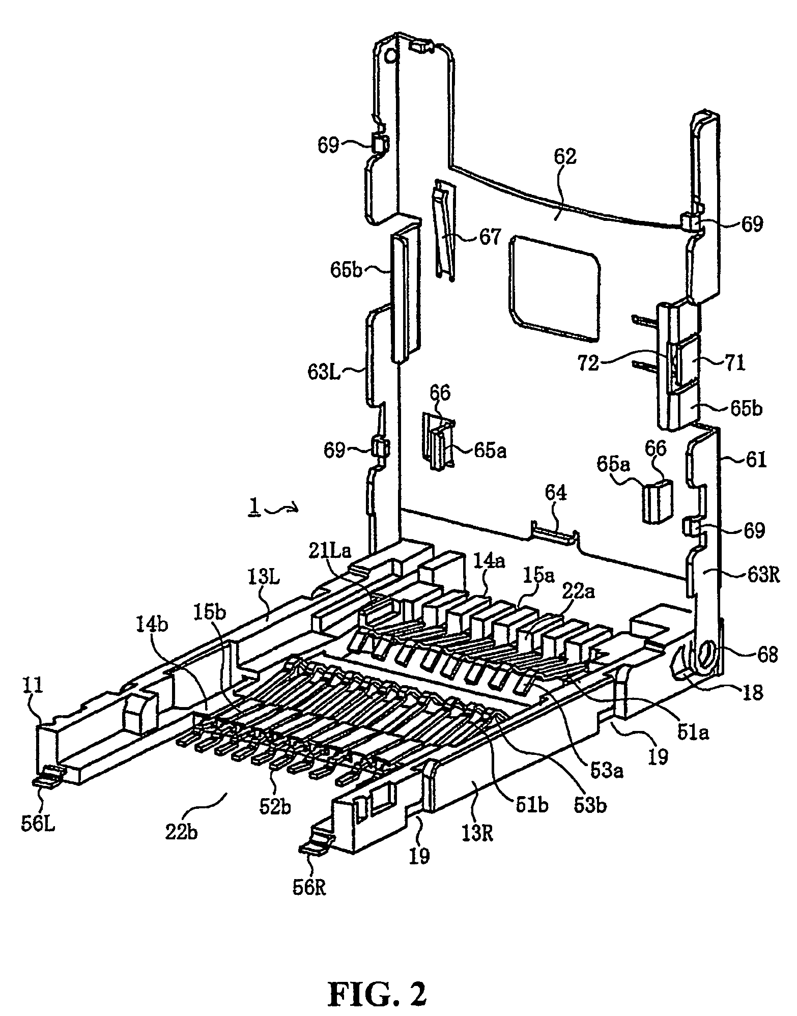
[0104]The present embodiment is described as another example of a card connector 1, which allows any one of “n” types of cards to be exclusively mounted therein, and “n” is 4 (four) in this case. This means, in the card connector 1 according to this embodiment, any one of the first card 101a, the second card 101b, and additional two types of cards, in other words, a third card 101c as a third type of card and a fourth card 101d as a fourth type of card can be exclusively mounted. The first card 101a to the fourth card 101d may be any types of cards, but the present embodiment is described as a case where the first card 101a and the second card 101b are a micro SD® card and a memory stick Micro®, respectively, like the first embodiment, and the third card 101c is a mini SD® card, and the fourth card 101d is a SD® card.
[0105]In this embodiment, the first card 101a has the smallest width, the second card 101b has a larger width than the first card 101a, the third card 101c has a larger...
second embodiment
[0120]Referring to FIGS. 19-22, the card connector of the second embodiment is shown with the shell 61 at the open position and with different cards inserted therein. More specifically, FIG. 19 shows the first card 101a retained in shell 61 with the front end face 116a engaging end positioning projection 64 to position the card 101a in a front to back direction and the side face portions 117a engaging the first card side face holding projections 65a to position card 101a in the width direction.
[0121]FIG. 20 shows the second card 101b retained in shell 61 with the front end face 116b thereof engaging first card side face holding projections 65a to position the card 101b in a front to back direction and the side face portions 117b engaging the second card side face holding projections 65b to position second card 101b in the width direction.
[0122]Similarly, FIG. 21 shows the third card 101c retained in shell 61 with the front end face 116c thereof engaging second card side face holding...
third embodiment
[0130]In the third embodiment, first card side face holding projection 65a through fourth card side face holding projections 65d on either the left or right side of shell 61 are arrayed along a straight line extending in the front and rear direction of a shell 61. In the illustrated example, the card side face holding projections on the right side are arrayed along the straight line adjacent the right side edge of the shell 61. The end positioning projection 64 is provided at a position corresponding to a position located between the paired first card side face holding projections 65a.
[0131]Comparing FIGS. 25-28 to FIGS. 19-22, it can be seen that the cards are retained in an identical manner in the third embodiment compared to the second embodiment but with the cards aligned adjacent the right side of shell 61 in the third embodiment. More specifically, the first card 101a is retained between first card side holding projections 65a and insertion is stopped by end positioning proje...
PUM
 Abstract
Description
Claims
Application Information
 - R&D
- Intellectual Property
- Life Sciences
- Materials
- Tech Scout
- Unparalleled Data Quality
- Higher Quality Content
- 60% Fewer Hallucinations
Browse by: Latest US Patents, China's latest patents, Technical Efficacy Thesaurus, Application Domain, Technology Topic, Popular Technical Reports.
© 2025 PatSnap. All rights reserved.Legal|Privacy policy|Modern Slavery Act Transparency Statement|Sitemap|About US| Contact US: help@patsnap.com


