Mounting unit for electromagnetic contactor and connection structure of electromagnetic contactor using the same

a technology of mounting unit and connection structure, which is applied in the direction of electromagnetic relay details, electrical apparatus, electromagnetic relays, etc., can solve problems such as erroneous mounting, and achieve the effect of preventing the mounting of non-mountable units and reliably mounting

Inactive Publication Date: 2013-08-20
FUJI ELECTRIC FA COMPONENTS & SYST CO LTD
View PDF15 Cites 9 Cited by
  • Summary
  • Abstract
  • Description
  • Claims
  • Application Information

AI Technical Summary

Benefits of technology

[0016]With such a configuration, since the mounting preventing transfer portion is movably provided at the unit main body, where the mounting preventing transfer member engages with the contactor-side mounting preventing portion formed at the unit mounting portion of the electromagnetic contactor, the unit-side mounting preventing portion identical to the contactor-side mounting preventing portion is formed at the unit mounting portion and erroneous mounting of the non-mountable unit on the unit mounting portion is prevented.
[0018]With such a configuration, in the case in which a non-mountable unit is mounted on the unit mounting portion of the mounting unit for an electromagnetic contactor in a state after the mounting unit for electromagnetic contactors has been mounted on the unit mounting portion of the electromagnetic contactor, when the non-mountable unit is caused to move along the unit mounting portion in a state after the hook piece of the non-mountable unit has been locked to the linking hole of the unit mounting portion, the mounting preventing engagement portion formed at the unit mounting portion rapidly abuts on the non-mountable unit, a state with a tilted non-mountable unit is assumed, and the erroneous mounting state can be reliably visually identified.
[0020]With such a configuration, since the mounting unit for an electromagnetic contactor is mounted over a plurality of unit mounting portions of electromagnetic contactors, it is possible to configure a reversible unit having an interlock mechanism that prohibits simultaneous loading of electromagnetic contactors.
[0022]With such a configuration, where the mounting preventing transfer member engages with the contactor-side mounting preventing portion in a state after the mountable unit has been mounted on the electromagnetic contactor, the unit-side mounting preventing portion is formed at the unit mounting portion of the mountable unit and mounting of the non-mountable unit can be prevented.

Problems solved by technology

However, the electromagnetic contactor described in Patent Document 1 mentioned hereinabove is a device designed specifically for mounting only the reversible unit and is not supposed to be used for mounting other mounting units such as the auxiliary contact unit via the reversible unit.
However, since there are mountable auxiliary contact units and non-mountable auxiliary contact units depending on the configuration of the electromagnetic contactor, an erroneous mounting preventing mechanism is provided that allows the mountable auxiliary contact units to be mounted on the electromagnetic contactor and prevents the erroneous mounting of the non-mountable auxiliary contact units.
The erroneous mounting preventing mechanism allows a mountable unit to be mounted on the unit mounting portion and prevents a non-mountable unit, which cannot be mounted, from being mounted on the unit mounting portion.
However, the following unresolved problem is associated with the reversible unit to be mounted between the electromagnetic contactor and the auxiliary contact unit.

Method used


Image

  • Mounting unit for electromagnetic contactor and connection structure of electromagnetic contactor using the same
  • Mounting unit for electromagnetic contactor and connection structure of electromagnetic contactor using the same
  • Mounting unit for electromagnetic contactor and connection structure of electromagnetic contactor using the same

Examples


Embodiment Construction

[0036]An embodiment of the present invention will be described below with reference to the appended drawings.

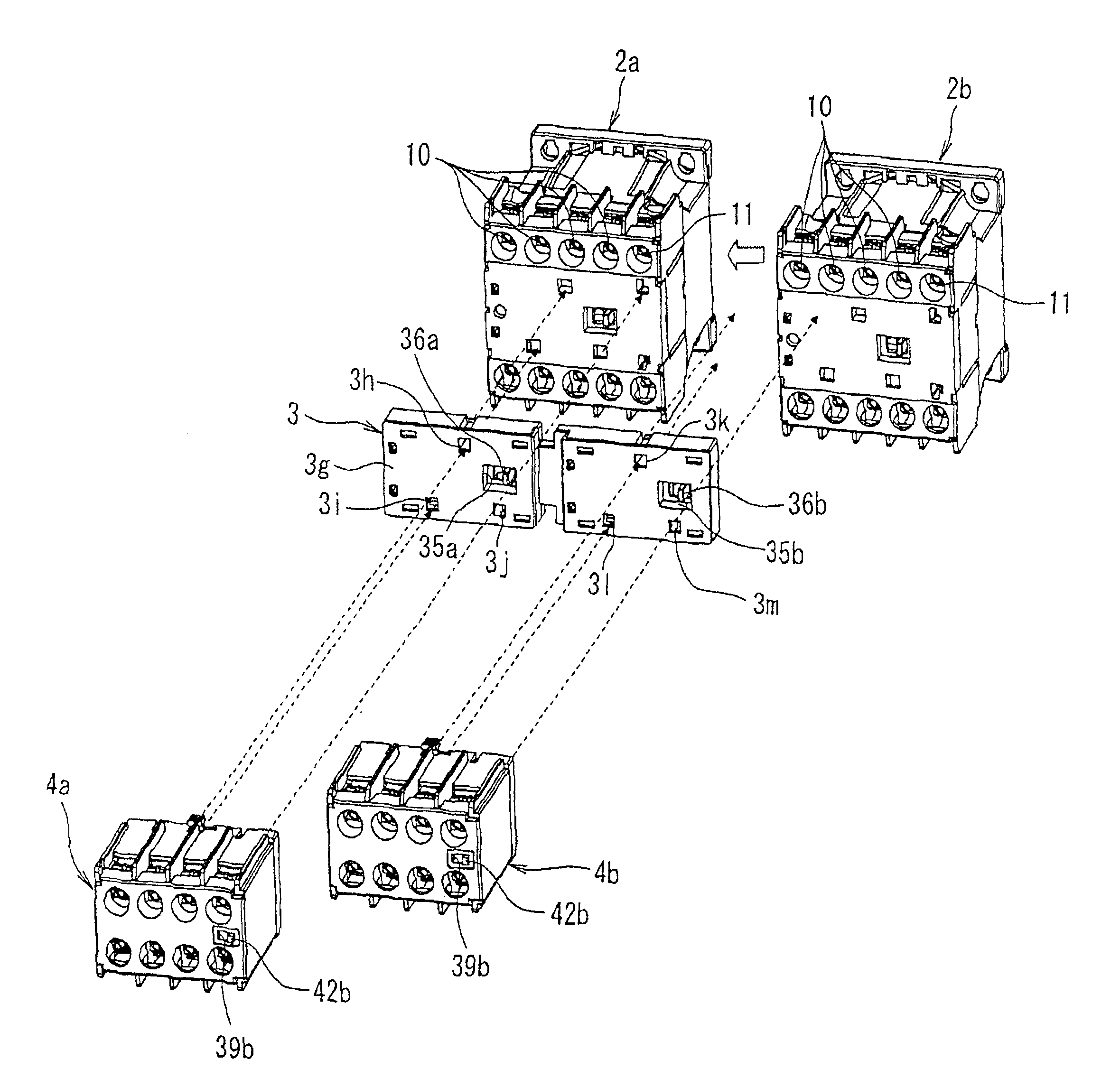
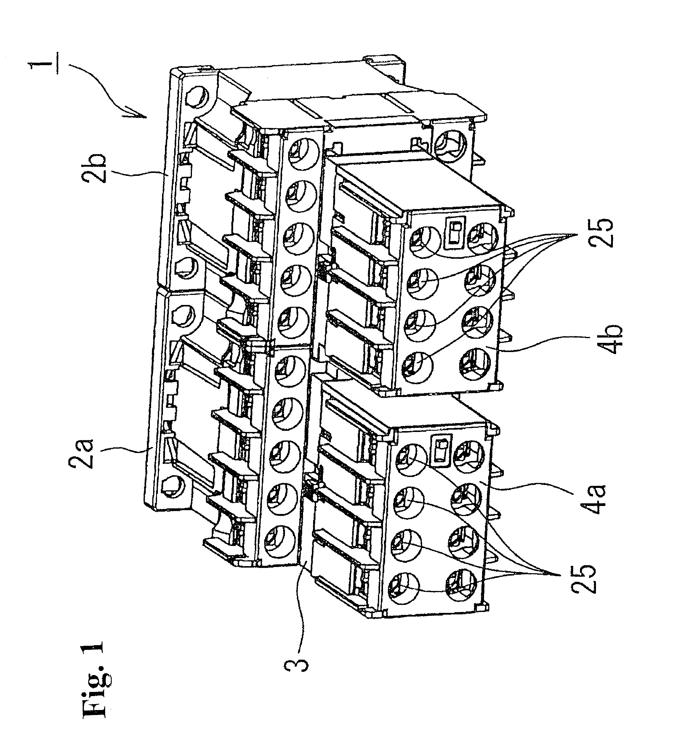
[0037]FIG. 1 is a perspective view illustrating an electromagnetic contactor device that is connected to a power feed circuit of a three-phase induction motor (not shown in the figure) and performs forward reverse control of the induction motor. An electromagnetic contactor device 1 is constituted by two electromagnetic contactors 2a, 2b, one reversible unit 3, two auxiliary contact units 4a, 4b serving as mountable units, and two auxiliary contact units 5a, 5b serving as non-mountable units.

[0038]Among the two electromagnetic contactors 2a, 2b, one electromagnetic contactor 2a is an electromagnetic contactor that performs forward control of the induction motor, and the other electromagnetic contactor 2b is an electromagnetic contactor that performs reverse control of the induction motor.

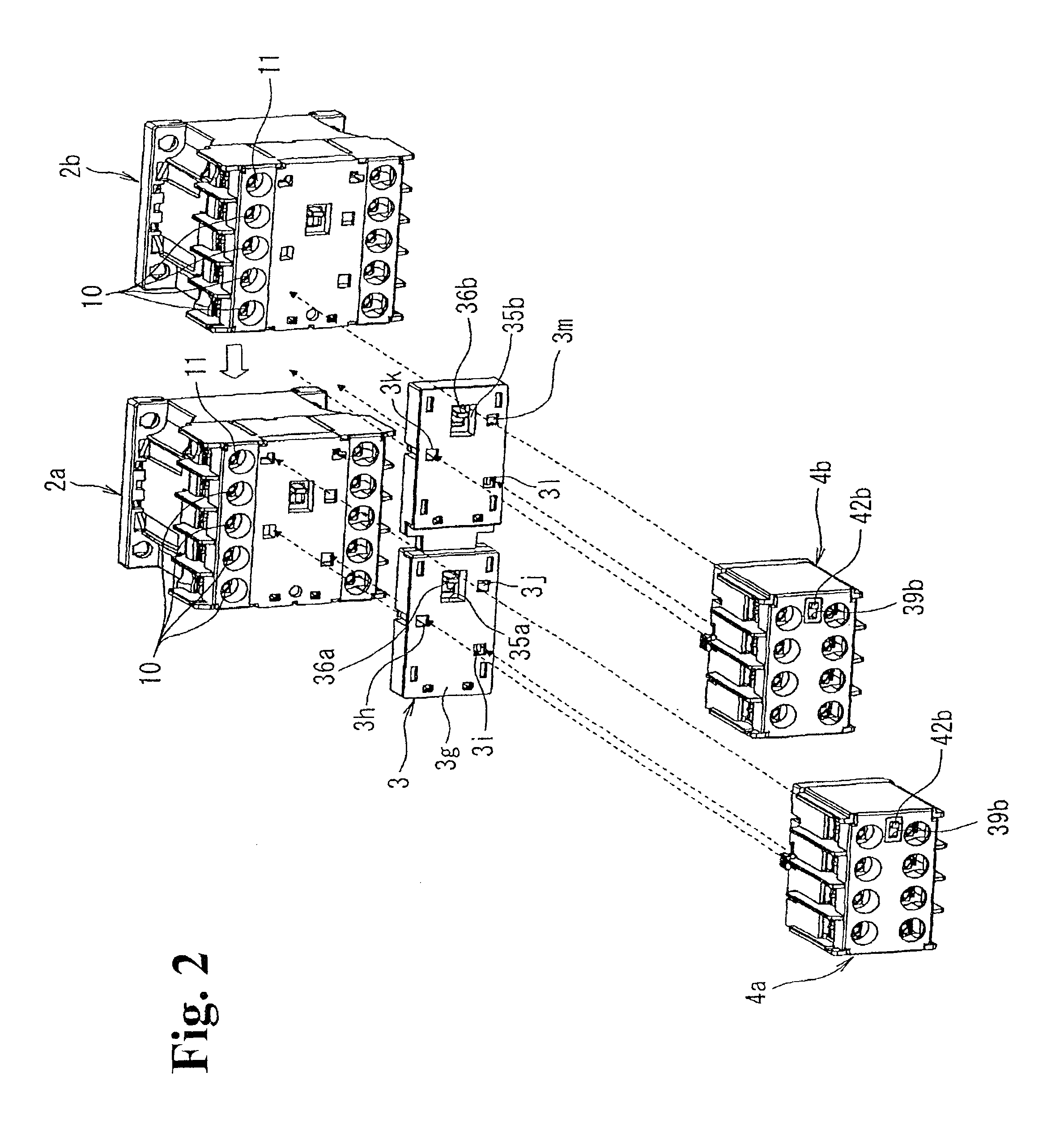
[0039]As shown in FIG. 2, the electromagnetic contactor 2a is a device provided with term...


PUM


Abstract

A mounting unit for an electromagnetic contactor can prevent erroneous mounting of a non-mountable unit in a state in which a mountable unit is mounted on a case-side mounting portion, and a connection structure of an electromagnetic contactor uses the mounting unit. A mounting unit (3) for an electromagnetic contactor can be mounted on electromagnetic contactors (2a, 2b) having on a unit attaching portion (6b) a contactor-side mounting preventing portion (6f) that prevents mounting by engagement when a non-mountable unit, which cannot be mounted, is mounted. In the mounting unit (3), a unit main body (39) is provided with a mounting preventing transfer member (51) that forms a unit-side mounting preventing portion (54) that engages with a contactor-side mounting preventing portion (6f) when mounted on the electromagnetic contactors (2a, 2b) and prevents mounting of the non-mountable unit on a unit mounting portion (3g) onto which the non-mountable units (5a, 5b) are mounted.

Description

RELATED APPLICATIONS[0001]The present application is National Phase of International Application No. PCT / JP2010 / 005583 filed Sep. 13, 2010, and claims priority from Japanese Application No. 2010-005509, filed Jan. 14, 2010.TECHNICAL FIELD[0002]The present invention relates to a mounting unit for an electromagnetic contactor that is mounted on the electromagnetic contactor when desired by the user and to a connection structure of the electromagnetic contactor using the mounting unit.BACKGROUND ART[0003]For example, the device described in Patent Document 1 is known as a mounting unit to be mounted on an electromagnetic contactor. This device has a pair of electromagnetic contactors having an excitation coil, a normally closed contact and a normally open contact, and also terminals thereof and are disposed in parallel to one another and an interlock block serving as a reversible unit that has connection terminals for connecting to the terminals of the aforementioned electromagnetic co...

Claims


Application Information

Patent Timeline
Patent Type & Authority Patents(United States)
IPC IPC(8): H01H9/00H01H13/04
CPCH01H50/323H01H50/541H01H2300/042
Inventor NAKA, YASUHIROOKUBO, KOJITAKAYA, KOUETSUSUZUKI, KENJI
Owner FUJI ELECTRIC FA COMPONENTS & SYST CO LTD
Why Eureka
Try Eureka