Attachment for a handheld appliance

a handheld appliance and attachment technology, applied in the direction of air heaters, lighting and heating apparatus, apparel, etc., can solve the problems of uncomfortable touch of the outer surface of the attachment, the blocked outlet of the attachment,

Active Publication Date: 2017-11-07
DYSON TECH LTD
View PDF182 Cites 51 Cited by
  • Summary
  • Abstract
  • Description
  • Claims
  • Application Information

AI Technical Summary

Benefits of technology

[0044]Preferably, the attachment further comprises an inner wall and the inner wall extends across the further fluid outlet reducing the further fluid flow that is drawn into the further fluid flow path.

Problems solved by technology

The fluid outlet of the attachment can become blocked and this is undesirable as blockage can cause damage to the fan unit that produced the fluid flowing through the attachment.
The fluid flowing through the attachment is often heated causing the outer surface of the attachment to become uncomfortably hot to touch.

Method used


Image

  • Attachment for a handheld appliance
  • Attachment for a handheld appliance
  • Attachment for a handheld appliance

Examples


Embodiment Construction

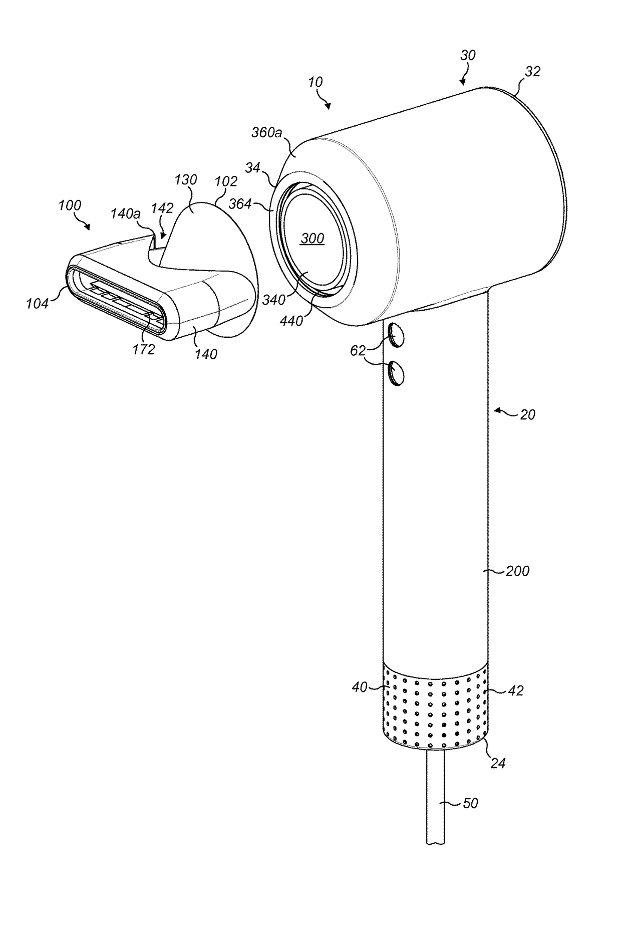
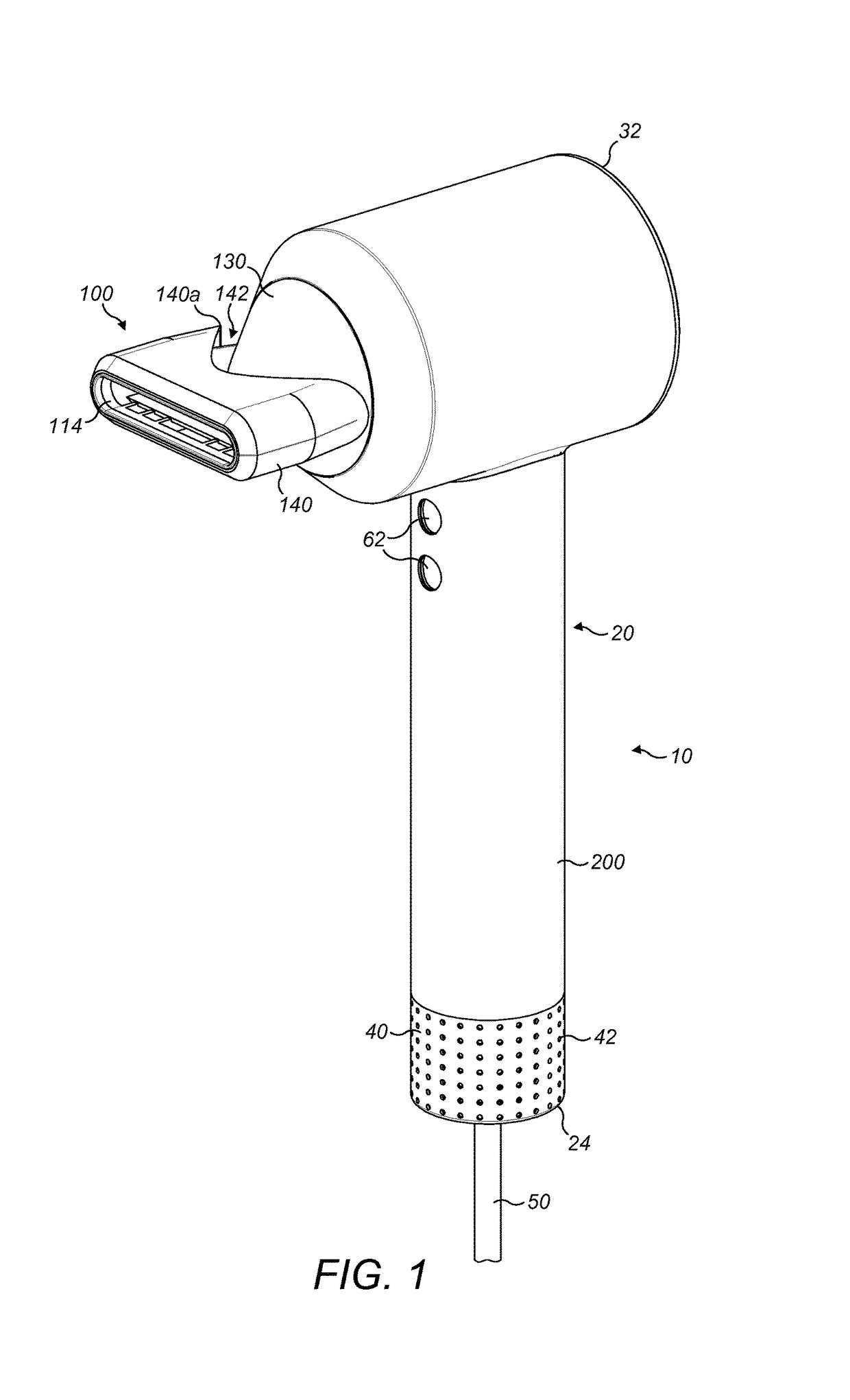
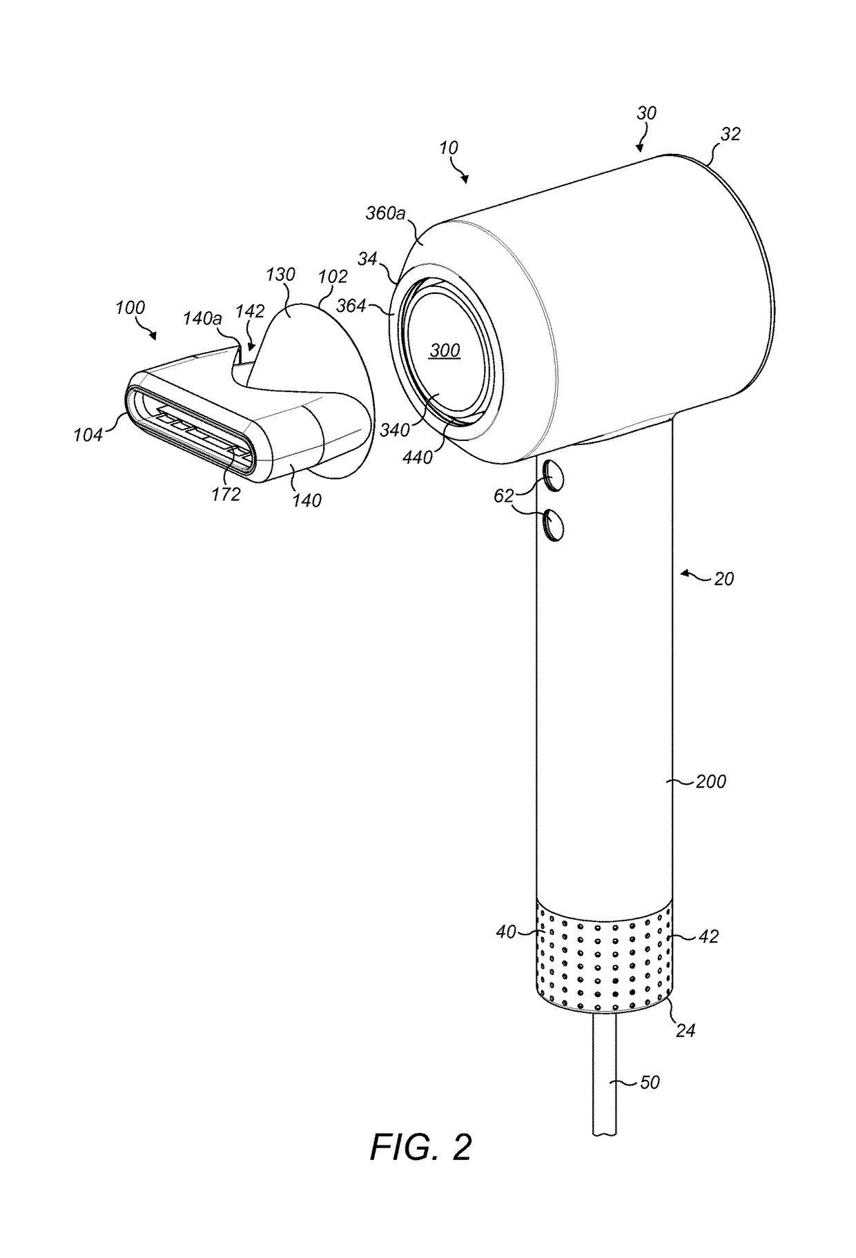
[0070]FIGS. 1 to 4 show a hairdryer 10 and an attachment 100. The hairdryer has a handle 20 and a body 30. The body has a first end 32 and a second end 34. Referring in particular to FIG. 4, the handle 20 has an outer wall 200 which extends from the body 30 to a distal end 24 of the handle. At the distal end 24 of the handle an end wall 210 extends across the outer wall 200. The cable 50 enters the hairdryer through this end wall 210. The handle 20 includes a primary inlet 40 having first apertures that extend around and along 42 the outer wall 200 of the handle and second apertures that extend across 46 and through the end wall 210 of the handle 20. The cable 50 is located approximately in the middle of the end wall 210 so extends from the centre of the handle 20. The end wall 210 is orthogonal to the outer wall 200 of the handle.

[0071]Referring in particular to FIG. 4, upstream of the primary inlet 40, a fan unit 70 is provided. The fan unit 70 includes a fan and a motor. The fan ...


PUM


Abstract

An attachment for a handheld appliance, the attachment having a first end for connection to the appliance and a second end, a first wall extending from the first end towards the second end and defining a fluid flow path through the attachment, a second wall extending from the second end towards the first end about the first wall and defining a second fluid flow path extending between the first wall and the second wall. The first end of the appliance may be substantially circular. The fluid flow path may have a fluid inlet that may be annular at the first end. The fluid inlet may be defined by the first wall and an inner wall extending around and at least partially along the first wall. The inner wall may be substantially equidistant from the first wall around the fluid inlet. A hair care appliance comprises such as attachment.

Description

REFERENCE TO RELATED APPLICATIONS[0001]This application claims the priority of United Kingdom Application No. 1313193.3 filed Jul. 24, 2013, the entire contents of which are incorporated herein by reference.FIELD OF THE INVENTION[0002]This invention relates to an attachment for a handheld appliance, in particular it relates to an attachment for a hair care appliance such as a hairdryer.BACKGROUND OF THE INVENTION[0003]Removable attachments for hairdryer can have a number of different uses. The usually circular flow exiting the hairdryer can be concentrated and flattened using a concentrator nozzle / attachment or it can be expanded and slowed by a diffuser. The different types of attachment dry the hair at different speeds with different flow rates enabling different styles to be created.[0004]The fluid outlet of the attachment can become blocked and this is undesirable as blockage can cause damage to the fan unit that produced the fluid flowing through the attachment.[0005]The fluid ...

Claims


Application Information

Patent Timeline
Patent Type & Authority Patents(United States)
IPC IPC(8): A45D20/12F24H3/04A45D20/10
CPCA45D20/12F24H3/0423A45D20/122A45D20/10
Inventor SUTTER, CATRIONA ANN CRAWLEYSMITH, STEPHEN FARRARSHELTON, EDWARD SEBERT MAURICEMOLONEY, PATRICK JOSEPH WILLIAM
Owner DYSON TECH LTD
Why Eureka
Try Eureka