Intraluminal vascular prosthesis

a vascular prosthesis and intraluminal technology, applied in the direction of tubular organ implants, stents, blood vessels, etc., can solve the problems of affecting the safety of patients, so as to achieve the effect of safe stabilization and significantly less risk of intervention

Active Publication Date: 2017-12-05
JOTEC
View PDF22 Cites 6 Cited by
  • Summary
  • Abstract
  • Description
  • Claims
  • Application Information

AI Technical Summary

Benefits of technology

[0012]By means of the inventive combination of two relatively short vascular prosthesis portions, i.e. a first one constituting a vascular prosthesis portion covered with prosthesis material and a second one composed only of prosthesis material, with a free and uncovered stent portion lying between these vascular prosthesis portions, it is possible to treat the three portions of the aorta, namely the ascending aorta, the aortic arch and the descending aorta, simultaneously and thus significantly reduce the time needed for the surgical intervention. It is thus possible to dispense with resection of the aortic arch, and with all the associated complex perfusion requirements for the brain and lower body, and the intervention can be carried out simply by separating the uppermost portion of the ascending aorta in a short (ca. 10-20 minute) selective head perfusion phase or hypothermic arrest phase in order to insert and release the new vascular prosthesis. It can be inserted and released simply with monitoring by the naked eye or by angioscope.
[0034]Particularly in the case of a dissection or complex aneurysm of the thoracic aorta, the surgical outlay and time involved is therefore a third of that needed for operations and systems used hitherto in the prior art, with comparable results, and therefore the risk of the intervention can be significantly lessened.

Problems solved by technology

Non-treatment of an aneurysm may lead to a rupture of the artery in advanced stages, after which the patient suffers internal bleeding.
Such surgery has generally required two major interventions to be performed at different times and entails a very extensive, complex and therefore dangerous operation, since it is not just the heart but also the brain and the abdominal organs of the patient that have to be subjected to hypothermic perfusion, i.e. artificial, cold extracorporeal blood flow.
However, only a small number of heart surgeons at specialist centers are sufficiently familiar with such a procedure.

Method used


Image

  • Intraluminal vascular prosthesis
  • Intraluminal vascular prosthesis
  • Intraluminal vascular prosthesis

Examples


embodiment 10

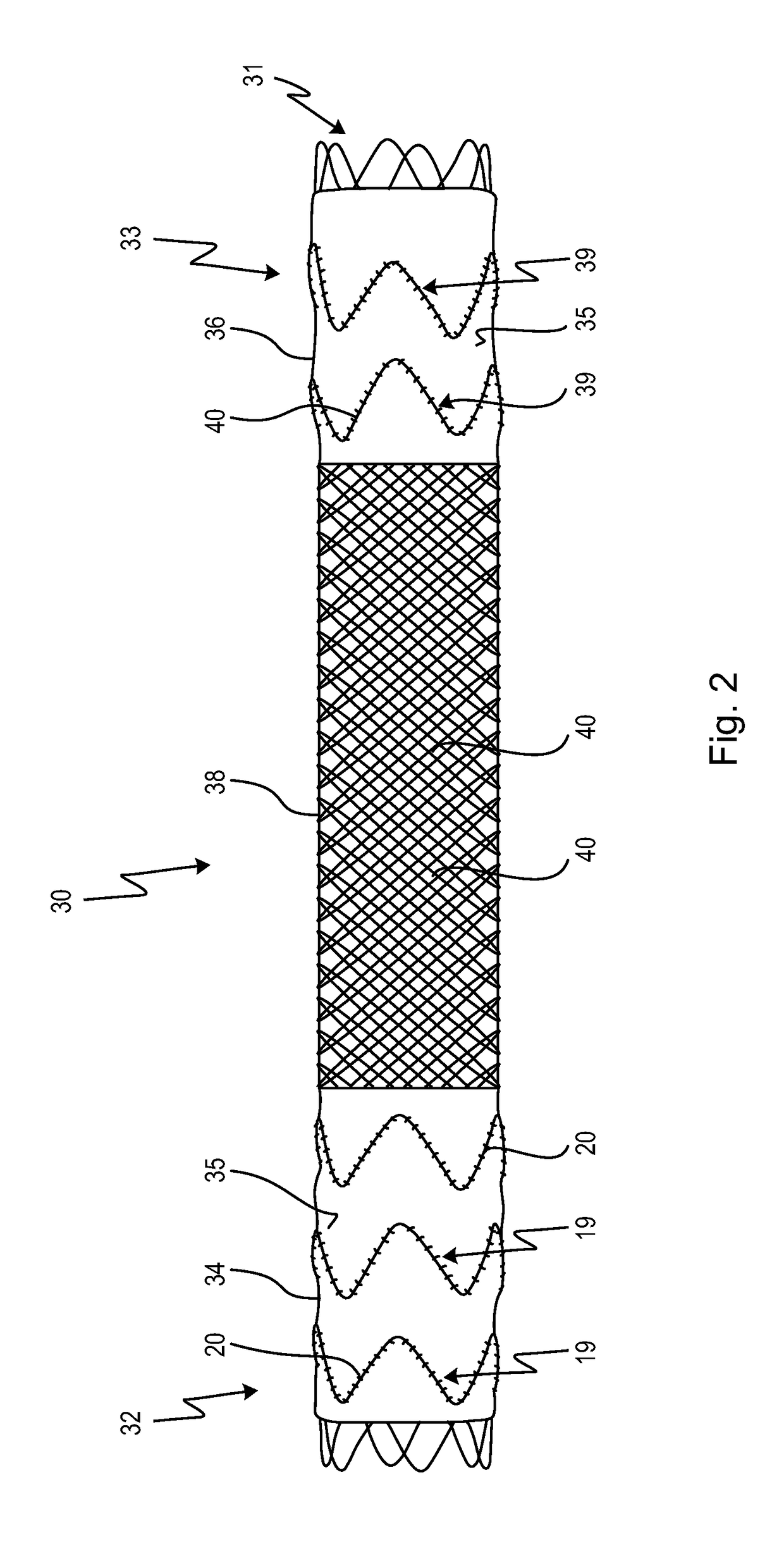
[0047]FIG. 2 shows a further embodiment of a vascular prosthesis 30 according to the invention, where features the same as those of the vascular prosthesis 10 in FIG. 1 are provided with the same reference signs. The vascular prosthesis 30 also has a hollow cylindrical body 31 and a distal end 32 and proximal end 33, and it also has a first vascular prosthesis portion 34 and a second vascular prosthesis portion 36. Like the first stent graft portion 14 of the embodiment 10 shown in FIG. 1, the first vascular prosthesis portion 34 has successive rings 19 of meandering supports 20, which are interconnected by a prosthesis material 35. Moreover, a stent portion that is free of prosthesis material and that has open cells or openings 40 is indicated by 38.

embodiment 30

[0048]The embodiment 30 shown in FIG. 2 has a second vascular prosthesis portion 36 which, like the first vascular prosthesis portion 34 in this embodiment, has successive rings 19 of meandering supports 20 and is covered by a prosthesis material 35 connecting the rings 19. As in FIG. 1, the first vascular prosthesis portion 34 constitutes a distal vascular prosthesis portion, the stent portion 38 constitutes the central vascular prosthesis portion, and the second vascular prosthesis portion 36 constitutes the proximal vascular prosthesis portion.

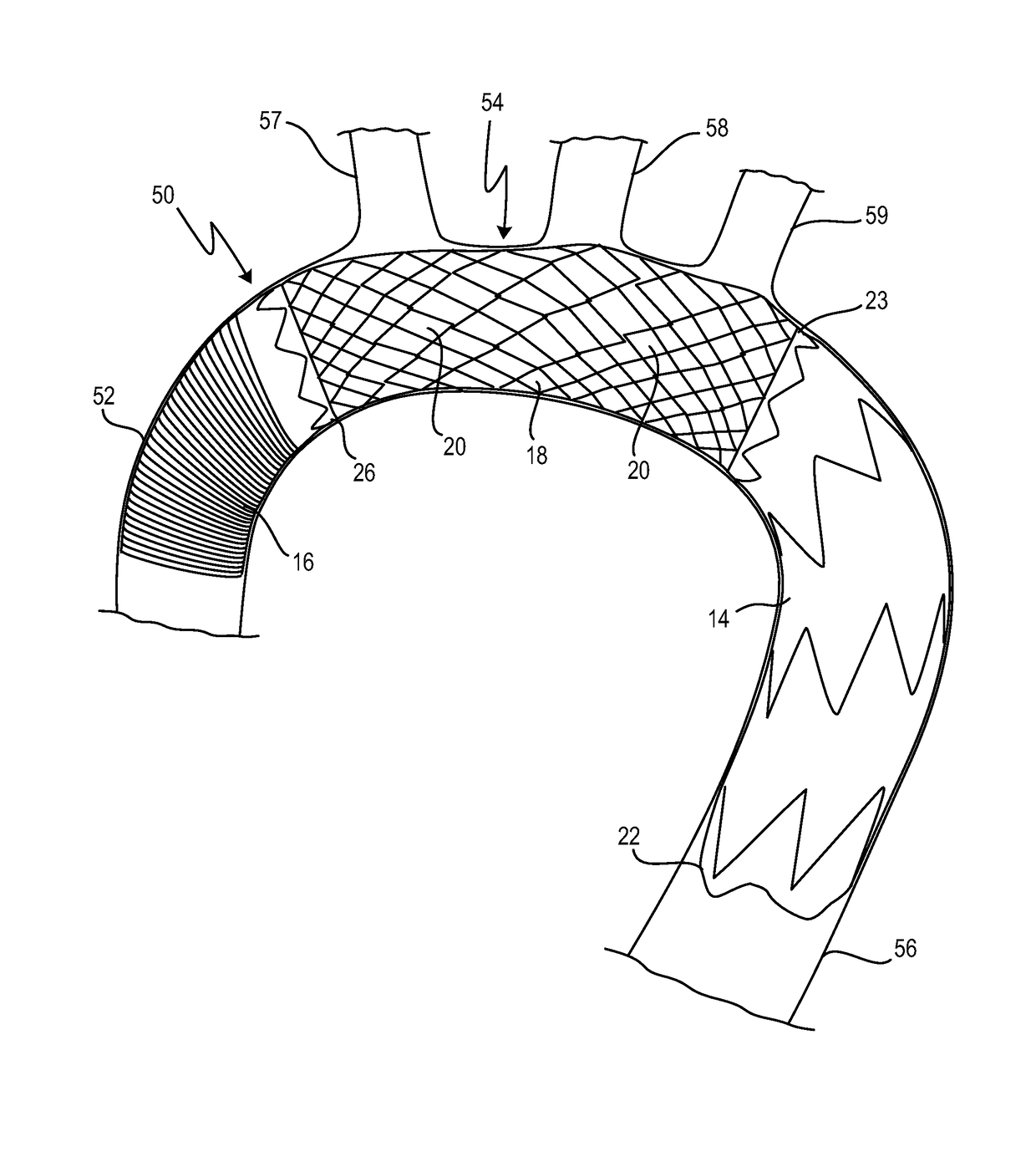
[0049]Finally, in FIG. 3, the embodiment of the vascular prosthesis according to the invention depicted in FIG. 1 is shown in a state when inserted into an aorta 50. In FIG. 3, reference sign 52 designates a part of the ascending aorta, 54 designates the aortic arch, and 56 designates the descending aorta. As will be seen from FIG. 3, three vessels 57, 58 and 59 branch off in the area of the aortic arch 54, namely the brachiocephalic trunk ...


PUM


Abstract

The invention relates to an intraluminal vascular prosthesis, preferably for implanting in the aortic arch. The prosthesis has a hollow cylindrical body with a first end and a second end; a first vascular prosthesis portion; a second vascular prosthesis portion; and a stent portion which is provided between the first and the second vascular prosthesis portion and which is rigidly connected to said vascular prosthesis portions, said stent portion being free of prosthesis material.

Description

CROSSREFERENCES TO RELATED APPLICATIONS[0001]This application is a continuation of international patent application PCT / EP2013 / 052037, filed on Feb. 1, 2013 designating the U.S., which international patent application has been published in German language and claims priority from German patent application DE 10 2012 100 839.6, filed on Feb. 1, 2012. The entire contents of these priority applications are incorporated herein by reference.BACKGROUND OF THE INVENTION[0002]The present invention relates to an intraluminal vascular prosthesis, in particular for implanting in the aortic arch, having a hollow cylindrical body with a first end and a second end, wherein the vascular prosthesis has, at its first end, a first vascular prosthesis portion, with successive rings of meandering supports, and a prosthesis material secured on the rings and connecting them.[0003]In particular, the present invention relates to vascular prostheses that are implanted in the area of the aortic arch.[0004]It...

Claims


Application Information

Patent Timeline
Patent Type & Authority Patents(United States)
IPC IPC(8): A61F2/06A61F2/82A61F2/07A61F2/89A61F2/90A61F2/91A61F2/915
CPCA61F2/82A61F2/07A61F2/89A61F2002/9155A61F2/91A61F2002/072A61F2/90
Inventor BOGENSCHUETZ, THOMASBARTHOLD, FRANZ-PETER
Owner JOTEC
Why Eureka
Try Eureka